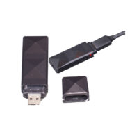


Active RFID tag reading module Customize your own reader to locate base station IPX antenna interface WE-RM01

Product Features
◆Stamp hole package for easy production integration, two antenna types to choose from.
◆Can detect 500 electronic tags at the same time, and the detection distance can be up to 100 meters in the open.
◆ It can measure the wireless signal field strength of the electronic tag and calculate the actual distance of the tag.
◆ Can call 10 tags simultaneously for audible and visual alerts (audible and visual tags only)
◆ Use TTL level serial port to communicate with the main controller, and various baud rates can be set.
◆Supports sleep mode with sleep current as low as 10uA.
◆A USB evaluation board is available to connect to a PC, which runs open source software to find peripheral tags.
◆2-3.6V wide voltage power supply, the maximum working current does not exceed 100mA.
◆Module operates in industrial grade temperature range of -40°C ~ +85°C
¥78
Product Overview
In order to make it easier for customers to integrate the card reader into their own devices, we have made the core function of the card reader into a stamp hole encapsulated module, which is only 16mm╳30mm in size, and is available in two different models: external antenna and on-board antenna.
Users as long as in their own circuit board mounted reader module, can easily have a long-distance range to read active electronic tags, not only can read the label ID, but also know the distance of the label, and quickly realize a variety of applications based on the label positioning technology program.
A number of readers work together, you can determine the effective range of the specific location of the electronic tags, to achieve real-time monitoring of the location of personnel, goods, to facilitate the tracking and finding of personnel, goods. Tag positioning is widely used in intelligent warehouse management, logistics tracking, indoor navigation, personnel management and many other applications.
The card reader module integrates a receiving antenna module, a low-noise amplifier module, a power supply module, and an external TTL level asynchronous serial communication interface, with a reading distance of up to 100 meters.
| Weight | 0.01 g |
|---|---|
| Positioning Properties |
specification
| sports event | norm | parameters |
|
wireless interface |
carrier frequency | 2.4GHz |
| modulation method | QPSK (Quad Phase Shift Keying) | |
| control protocols | IEEE 802.15.4 | |
| receiver sensitivity | -118dBm | |
| characteristic impedance | 50 ohms | |
| Antenna Interface | IPX (M01) | |
|
communications serial port |
communication protocols | Open Serial Protocol |
| Interface Specifications | TTL level serial port (TXD, RXD, GND) | |
| baud | 115200, 38400, 19200, 9600bps | |
| electric power source | input voltage | 2.0V~3.6V |
| amps | Less than 100mA | |
| Appearance Structure | sizes | 16mm╳30mm |
| thicknesses | 2.5mm | |
| working environment | temp | -40℃~ 85℃, -40℃~ 85℃, -40℃~ 85℃, -40℃~ 85℃ |
| humidity level | Less than 95% (no condensation) |
Pin Description
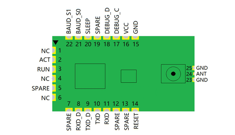
| pin number | name (of a thing) | clarification | descriptive |
| 1 | NC | unoccupied | Suggested Suspension |
| 2 | ACT | Activity instructions | Output, receiving a tag signal sends out a 50ms positive pulse (VLmax:0.4V, VHmin:2.4V) |
| 3 | RUN | running indication | output, the module sends out a 50ms positive pulse per second (VLmax:0.4V, VHmin:2.4V) |
| 4 | NC | unoccupied | Suggested Suspension |
| 5 | SPARE | reserve | Suggested Suspension |
| 6 | NC | unoccupied | Suggested Suspension |
| 7 | SPARE | reserve | Suggested Suspension |
| 8 | RXD_D | Debugging serial port (receive) | Input (VLmax:0.6V, VHmin:2.1V) |
| 9 | TXD_D | Debugging serial port (send) | Output (VLmax:0.4V, VHmin:2.4V) |
| 10 | TXD | Communication serial port (transmit) | Output (VLmax:0.4V, VHmin:2.4V) |
| 11 | RXD | Communication serial port (receive) | Input (VLmax:0.6V, VHmin:2.1V) |
| 12 | SPARE | reserve | Suggested Suspension |
| 13 | SPARE | reserve | Suggested Suspension |
| 14 | RESET | Module reset | Pull down the pin for more than 100ms to reset the module. (VLmax:0.6V, VHmin:2.1V) |
| 15 | GND | Power (Ground) | |
| 16 | VCC | Voltage (positive) | Module power supply, 3.3V recommended (2.0V~3.6V) |
| 17 | DEBUG_C | Debugging (clock) | For updating module firmware |
| 18 | DEBUG_D | Commissioning (data) | For updating module firmware |
| 19 | SPARE | reserve | Suggested Suspension |
| 20 | SLEEP | sleep control | Input (VLmax:0.6V, VHmin:2.1V), low level to sleep state (current less than 10uA) |
| 21 | BAUD_S0 | Serial port baud rate setting bit 0 | Setting the baud rate of the main serial port |
| 22 | BAUD_S1 | Serial baud rate setting 1 bit | |
| 23 | GND | antennae | Direct connection to signal ground possible (M01 module only) |
| 24 | ANT | connection with high-ranking officials | Instead of using the IPX antenna holder on the module, the external antenna is connected directly through the circuit board. |
| 25 | GND | antennae | Directly connectable to signal ground |
Related drawings
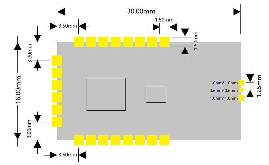
Package Size

When designing the backplane package, you only need to place a 1.5mm*1.5mm square pad at the corresponding position of the stamp hole pin, a 1.0mm*1.0mm pad at the corresponding position of the antenna ground, and a -0.6mm*0.6mm pad at the corresponding position of the antenna.
If the on-board antenna on the module is used, or if the IPX antenna holder on the module is used, the pads corresponding to the antenna can be designed without.
As shown in the figure below:
On-Board PCB Antenna Placement Instructions
Option 1 (recommended):
Place the module along the edge of the PCB with the on-board antenna outside the board frame.
Program 2:
Place the module PCB edge to edge, with the on-board antenna placed along the edge of the board and hollowed out underneath.
Program 3:
Place the module PCB edge to edge and the on-board antenna along the edge of the board without copper cladding.

IO Pin Alignment Recommendations
For some applications with high power consumption and EMI characteristics, it is recommended to connect 10~100 ohm resistors in series on the I/O lines. This will suppress overshoot and smooth out the signal when the power is switched on and off. Series resistors also provide some protection against electrostatic discharge (ESD).
Antenna recommendations from the circuit board
Instead of using the on-board PCB antenna and leading the antenna from the IPX antenna holder on the module, the antenna is led directly from the antenna pin of the module via the baseboard. When designing the antenna alignment on the baseboard, it is necessary to ensure that the ANT antenna has a line impedance of 50 ohms to achieve the best antenna signal transmission effect.
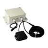
Related products

RFID Location Tag/Reader Module
Long-distance range active electronic label network reader WE-RN06
¥548