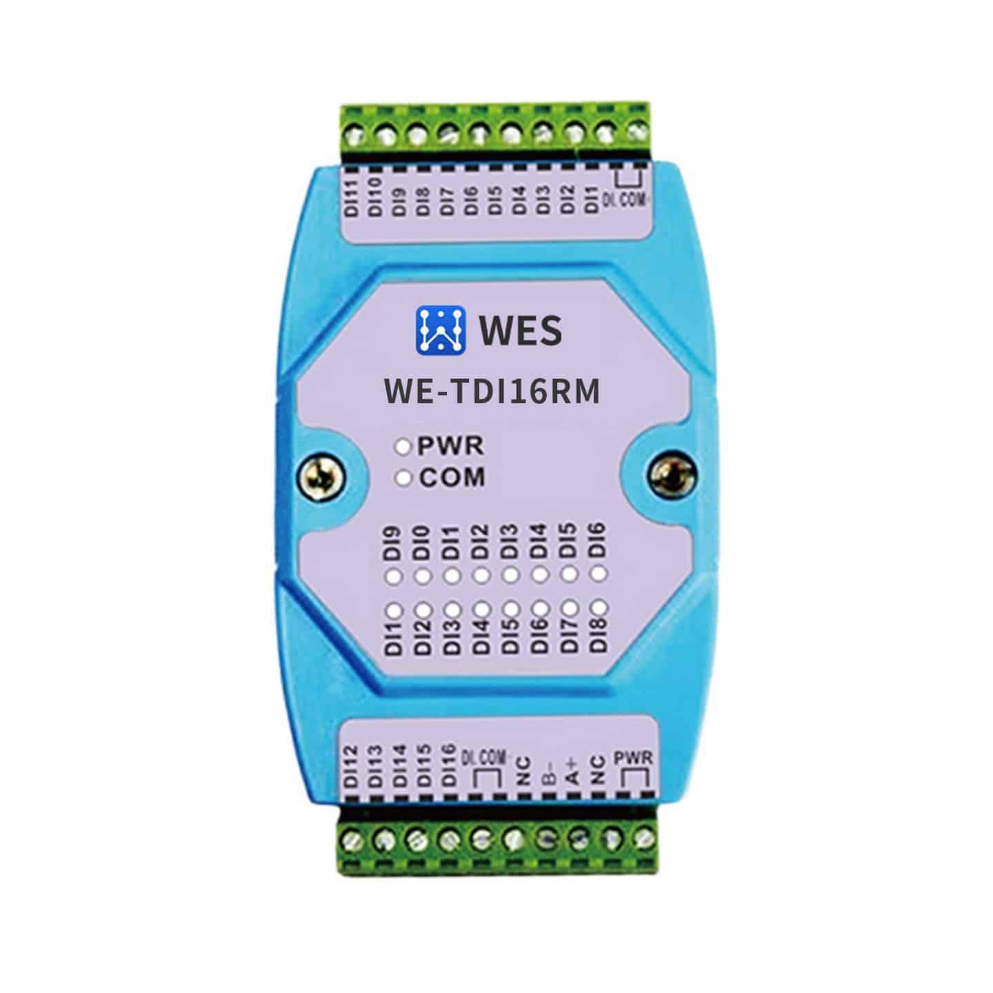
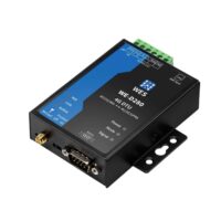
Industrial 16-channel digital input RS485 data wireless acquisition module WE-TDI16RM
Product Features
- 16 dry or wet node inputs
- Wet nodes support up to DV60V
- One 200 HZ counter per input channel
- Adoption of MODBUS RTU slave protocols
- RS485 bus supports up to 250 devices
- Power supply non-polarized input
- Abundant indicator lights for easy fault checking
- Supports power-on modification of MODBUS slave address and serial port attribute function
- The software can determine if the device is powered down or reset.
- Easy to install
¥350
FBT RS-485 industrial IO series supports the most commonly used I/O data acquisition protocols, which can be matched with various types of sensors, and is widely used in fire fighting, electric power, water supply, petrochemical, intelligent agriculture and other scenarios.FBT serial RS-485 uses the standard Modbus RTU/ASCII protocol, which can be easily interfaced with the SCADA system to upload on-site sensor data.
The FBTDI16RM utilizes the standard Modbus RTU slave communication protocol, allowing remote data acquisition via the RS485 bus, which can support up to 250 devices.
FBTDI16RM is a 16-channel digital input (DI) RS485 data acquisition module. 16-channel DI supports dry contact or digital signal input, wet node support up to DC60V, each input channel has a 200HZ counter.
| transportation protocol |
|---|
specification
| digital input | DI | 16 dry or wet node inputs |
| DI protection | 1500V voltage isolation | |
| One counter per DI | 200HZ: Duty Cycle 40%~60% | |
| 100HZ: Duty Cycle 30%~70% | ||
| Wet node input | Low level less than 1V, high level greater than 3.5V | |
| Overvoltage 60V, absorption current less than 8mA | ||
| bus interface | Interface Type | RS485 |
| baud | 1.2Kbps~115.2 Kbps | |
| data bit | 8 | |
| calibration | Supports no checksum, odd and even checksums | |
| stop bit | Supports 1, 1.5, 2 bits without parity | |
| Supports 1 bit with checksum | ||
| communication protocol | MODBUS RTU slave | |
| Bus protection | Isolation voltage 1500V; ESD 15KV; Surge protection: 600W | |
| electric power source | Input Voltage | DC9V~DC24V non-polarized input; |
| Power protection | Over-voltage protection: 60V; over-current protection: 800mA; | |
| Surge protection: 600W | ||
| Current consumption | 80mA@24V MAX | |
| working environment | Operating temperature, humidity | -25~75℃, 5~95%RH, no condensation |
| Storage temperature, humidity | -40~125℃, 5~95%RH, no condensation | |
| other than | Slave Address Range | 1~254 |
| sizes | 72.1*121.5*33.6mm | |
| Installation | Standard DIN rail mounting | |
| housings | ABS engineering plastics | |
| promise to keep sth. in good repair | 3 years |
blueprint


application connection
-
network topology
RS485 bus access to this device, should be in line with the RS485 bus wiring specification, using a hand in hand network topology to connect with other devices in the system, and at the end of the bus to join the matching resistance of about 120 ohms (as shown in the ideal connection diagram below). However, in the actual project, is in accordance with the actual connection diagram below for wiring, the figure D for the RS485 bus to the length of the branch line of the device, the length of D is strongly recommended to be less than 0.5 meters

Ideal Linkage Diagram

Actual connection diagram
-
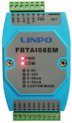
wiring terminal
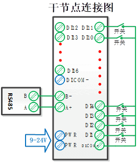
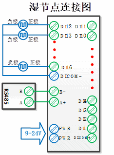
DI.COM+ Dry Node Input Common
DI1 to DI16 digital signal inputs
DI.COM- Wet Node Input Common
PWR (2-wire) Connects to positive and negative polarity of power supply, regardless of polarity
A+ RS485 signal A
B- RS485 signal B
NC Not Connected
-
LED indication
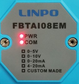
PWR Power indicator, always on when power is normal
COM communication indicator, the indicator is on when the serial port sends and receives data; however, when the RS485 bus fails or the serial port attributes are set incorrectly, the indicator will flash, the flash cycle is about 2 seconds.
DI1 to DI16 switching input status indicator: when the light is on, the corresponding signal is 1; when the light is off, the corresponding signal is 0
- Sensor connection method
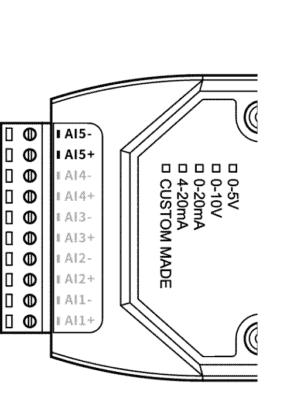
The FBTDI16RM supports wet and dry node wiring, and the module wiring is shown with each DI channel wired independently and sharing DI.COM terminals.


 Integrated Data Acquisition Gateway Switching Analog Single Bus Integrated Acquisition Transmission WE-T02