


Product Features
- Using the standard Modbus RTU slave communication protocol.
- Remote data acquisition via RS485 bus is possible.
- RS485 bus supports up to 250 devices
- is an 8-channel analog input serial data acquisition module.
- Power supply non-polarized input
- Abundant indicator lights for easy fault checking
- Support the function of power-on modification of network parameters
- It can input 0~5V, 0~10V, 0~20mA, 4~20mA analog signals respectively.
- Can be customized according to customer's needs.
¥350
Product Overview
The RS-485 Industrial IO series supports the most commonly used I/O data acquisition protocols and can be matched to various types of sensors.
FBTAI08RM adopts the standard Modbus TCP communication protocol and performs remote data acquisition through serial port RS485. This product has good expansion performance and is easy to use.FBTAI08EM supports MODBUS multiple function codes; FBTAI08EM supports free protocol auto upload function.
Application Industries
Widely used in firefighting, electric power, water supply, petrochemical, intelligent agriculture and other scenes
| input and output | 0~20mA, 4~20mA, 0~10V input, 0~5V input |
|---|---|
| transportation protocol |
specification
| Analog Input Interface | channel number | 8 |
| input protection | 2500V voltage isolation
Voltage input type: 60V DC overvoltage protection Current input type: no protection❷ |
|
| Input Impedance❶ | Voltage Input Type: 10M Ohms
Current input type: 249 ohms |
|
| sampling resolution | 12-bit AD conversion | |
| measurement error | 0.2% @250C full scale | |
| temperature drift | Less than 50ppm/0C | |
| Ethernet interface | Interface Type | RJ-45 |
| speed | 10M/100M Adaptive | |
| electric power source | Input Voltage | DC9V~DC24V non-polarized input; |
| Power protection | Over-voltage protection: 60V; over-current protection: 800mA;
Surge protection: 800W |
|
| Current consumption | 60mA@24V MAX | |
| working environment | Operating temperature, humidity | -25~65℃, 5~95%RH, no condensation |
| Storage temperature, humidity | -40~125℃, 5~95%RH, no condensation | |
| other than | slave address | slave address is meaningless |
| sizes | 72.1*121.5*33.6mm | |
| Installation | Standard DIN rail mounting | |
| housings | ABS engineering plastics | |
| promise to keep sth. in good repair | 3 years |
❶: As the device adopts active input impedance technology, it is wrong to use a multimeter to test the input impedance of the voltage input type module when the power is off. The way to measure the input impedance is to connect the measured signal source in series with a resistor of about 500K and then connect it to the device, and then test the voltage of the ends of the resistor that is connected in series after the power is turned on, and then according to Ohm's law, the input impedance can be measured. For current-type input module, you can directly use the resistance of the multimeter for impedance testing.
❷: For current-type input devices, do not connect a current source larger than 40mA to the analog inputs (AI+, AI-), and do not directly parallel a voltage source larger than 10V to AI+, AI-, as this will deteriorate the accuracy of the device and may even damage it.
blueprint
Product Size

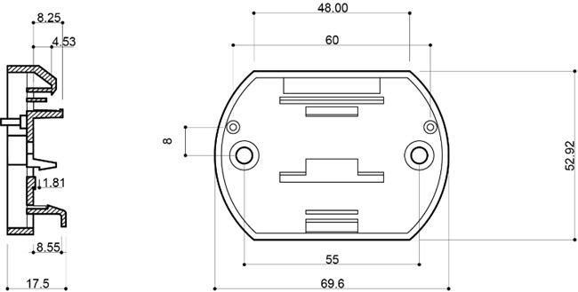
Installation


application connection
-
network topology
RS485 bus access to this device, should be in line with the RS485 bus wiring specification, using a hand in hand network topology to connect with other devices in the system, and at the end of the bus to join the matching resistance of about 120 ohms (as shown in the ideal connection diagram below). However, in the actual project, is in accordance with the actual connection diagram below for wiring, the figure D for the RS485 bus to the length of the branch line of the device, the length of D is strongly recommended to be less than 0.5 meters
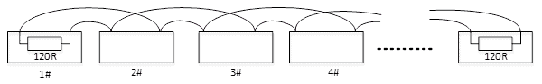
Ideal Linkage Diagram
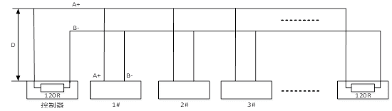
Actual connection diagram
-
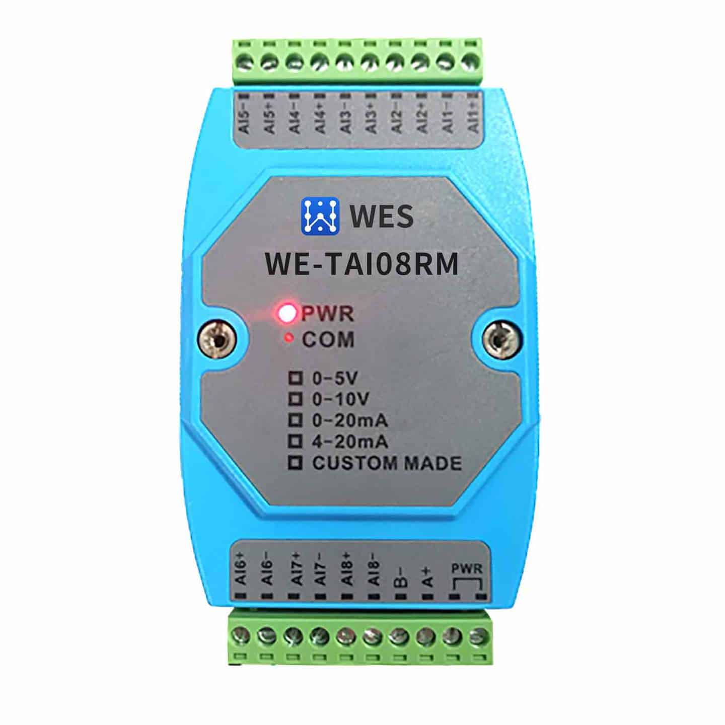
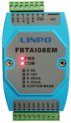
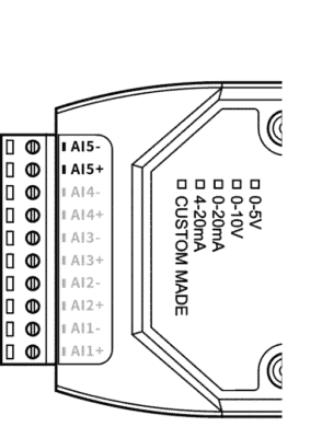
wiring terminal
AI1+ ~ AI8+ Analog Input Channels 1~8 Positive
AI1- ~ AI8- Analog Input Channel 1~8 Negative
PWR is connected to the positive and negative terminals of the power supply, regardless of polarity.
A+ RS485 signal A
B- RS485 signal B
-
LED indication

PWR Power indicator, always on when power is normal
COM communication indicator, the indicator is on when the serial port sends and receives data; however, when the RS485 bus fails or the serial port attributes are set incorrectly, the indicator will flash, the flash cycle is about 2 seconds.
- Sensor connection method
FBTAI08EM supports common analog modules, which can collect standard current and voltage signals. Current includes: 0-20mA, 4-20mA two kinds of signals, voltage includes: +/-5V, +/-10V three kinds of signals. The wiring terminals of the common analog module are shown in the figure below, and there are two terminals for each analog channel.
1, 4-wire sensor wiring
A four-wire signal means that the signal and power lines on an analog instrument or device add up to four wires. The instrument or device has a separate power supply, and in addition to the two power lines there are two signal lines. The wiring of a four-wire signal is shown in the following figure

A four-wire signal means that the signal and power lines on an analog instrument or device add up to four wires. The instrument or device has a separate power supply, and in addition to the two power lines there are two signal lines. The wiring of a four-wire signal is shown in the following figure
2, 3-wire sensor wiring
Analog voltage/current 3-wire wiring shown
Analog voltage/current 3-wire wiring shown
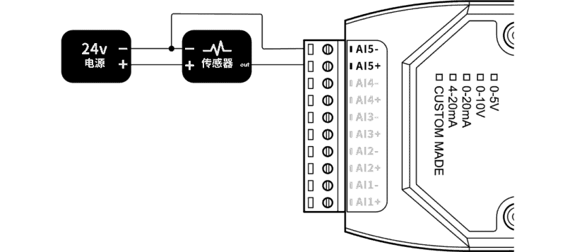
3, 2-wire sensor wiring
Two-wire signaling means that the signal and power wires on the instrument or device add up to only two terminals. Since the FBT Industrial IO analog module channels do not have a power supply, the instrument or device requires an external 24V DC power supply. Analog voltage/current two-wire wiring shown.
Two-wire signaling means that the signal and power wires on the instrument or device add up to only two terminals. Since the FBT Industrial IO analog module channels do not have a power supply, the instrument or device requires an external 24V DC power supply. Analog voltage/current two-wire wiring shown.
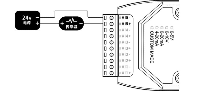
 Due to the extremely high input impedance of voltage input type devices, the conversion value of the unconnected input channel may be randomly jumped depending on the difference in device parameters, so it is recommended that AI+ and AI- of the unused input channel be short-circuited.
Related products


¥1,480 – ¥1,580
This product has multiple variants. The options may be chosen on the product page


serial port server
Industrial WiFi Serial Server RS232/485/422 to WiFi Dual Serial Ethernet Transmission WE-W220
¥235


Liquid Level Sensor
¥695 – ¥873
This product has multiple variants. The options may be chosen on the product page

Pressure sensors
¥601 – ¥780
This product has multiple variants. The options may be chosen on the product page