


Product Features
- 8-channel isolated analog signal input
- Adopts standard MODBUS TCP communication protocols
- Optional automatic upload mode.
- Auto upload mode can be configured as signal change upload and timed upload modes
- Power supply non-polarized input
- Abundant indicator lights for easy fault checking
- Reboot the device to modify the network parameter function
¥350
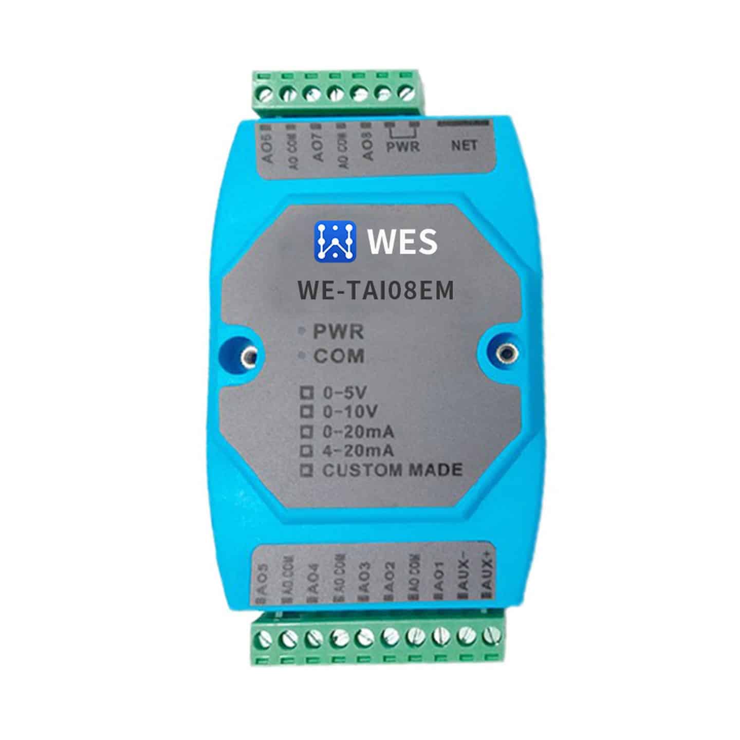
Product Overview
The Industrial Ethernet IO series supports the most commonly used I/O data acquisition protocols to match various types of sensors; FBT Ethernet IO uses the standard Modbus TCP protocol, which can be easily interfaced with SCADA systems to upload sensor data. Unlike the standard Modbus TCP protocol, FBT Ethernet IO sensors support active data reporting, which can be timed or detected changes, and actively upload data to a set target host via TCP or UDP protocol. This function has a faster response time, reducing the occupation of system resources and network resources; in addition, this function can be very convenient to upload the data to the cloud, to realize the cloud unified summary management.
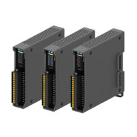
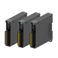
FBTAI08EM adopts standard Modbus TCP communication protocol for remote data acquisition via Ethernet. This product has good expansion performance and is easy to use.FBTAI08EM supports MODBUS multiple function codes; FBTAI08EM supports free protocol auto upload function.
FBTAI08EM supports 5 Modbus Slave terminals to access the data, FBTAI08EM is an 8-channel analog input Ethernet data acquisition module, FBTAI08EM has 4 sub-models, which can input 0~5V, 0~10V, 0~20mA, 4~20mA analog signals respectively.
Application Industries
Widely used in firefighting, electric power, water supply, petrochemical, intelligent agriculture and other scenes
| input and output | 0~20mA, 4~20mA, 0~10V input, 0~5V input |
|---|---|
| transportation protocol |
specification
| Analog Input Interface | channel number | 8 |
| input protection | 2500V voltage isolation
Voltage input type: 60V DC overvoltage protection Current input type: no protection❷ |
|
| Input Impedance❶ | Voltage Input Type: 10M Ohms
Current input type: 249 ohms |
|
| sampling resolution | 12-bit AD conversion | |
| measurement error | 0.2% @250C full scale | |
| temperature drift | Less than 50ppm/0C | |
| Ethernet interface | Interface Type | RJ-45 |
| speed | 10M/100M Adaptive | |
| electric power source | Input Voltage | DC9V~DC24V non-polarized input; |
| Power protection | Over-voltage protection: 60V; over-current protection: 800mA;
Surge protection: 800W |
|
| Current consumption | 60mA@24V MAX | |
| working environment | Operating temperature, humidity | -25~65℃, 5~95%RH, no condensation |
| Storage temperature, humidity | -40~125℃, 5~95%RH, no condensation | |
| other than | slave address | slave address is meaningless |
| sizes | 72.1*121.5*33.6mm | |
| Installation | Standard DIN rail mounting | |
| housings | ABS engineering plastics | |
| promise to keep sth. in good repair | 3 years |
❶: As the device adopts active input impedance technology, it is wrong to use a multimeter to test the input impedance of the voltage input type module when the power is off. The way to measure the input impedance is to connect the measured signal source in series with a resistor of about 500K and then connect it to the device, and then test the voltage of the ends of the resistor that is connected in series after the power is turned on, and then according to Ohm's law, the input impedance can be measured. For current-type input module, you can directly use the resistance of the multimeter for impedance testing.
❷: For current-type input devices, do not connect a current source larger than 40mA to the analog inputs (AI+, AI-), and do not directly parallel a voltage source larger than 10V to AI+, AI-, as this will deteriorate the accuracy of the device and may even damage it.
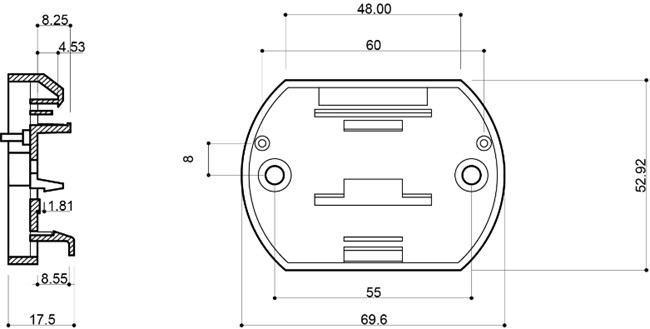
blueprint
Product Size

Installation


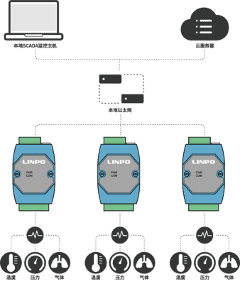
application connection
-
network topology
-
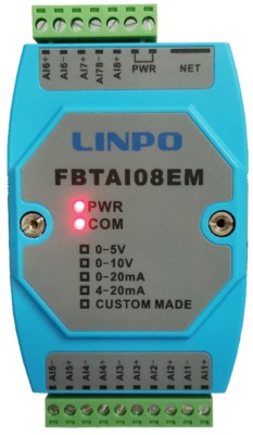
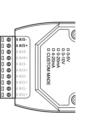
wiring terminal
NET: 10/100M network port
PWR: 9-24VDC, connected to positive and negative poles of the power supply respectively, regardless of polarity
AI1+ AI1-Analog Input Wiring
AI78- is the 7th and 8th analog common terminal.
-
LED indication
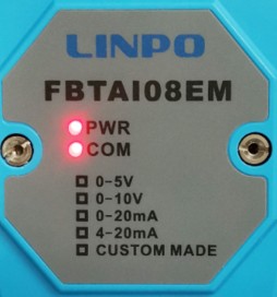
PWR Power indicator, always on when power is normal
COM communication indicator, lit when the connection is successful Flashes when data is sent.
- Sensor connection method
FBTAI08EM supports common analog modules, which can collect standard current and voltage signals. Current includes: 0-20mA, 4-20mA two kinds of signals, voltage includes: +/-5V, +/-10V three kinds of signals. The wiring terminals of the common analog module are shown in the figure below, and there are two terminals for each analog channel.
1, 4-wire sensor wiring
A four-wire signal means that the signal and power lines on an analog instrument or device add up to four wires. The instrument or device has a separate power supply, and in addition to the two power lines there are two signal lines. The wiring of a four-wire signal is shown in the following figure

A four-wire signal means that the signal and power lines on an analog instrument or device add up to four wires. The instrument or device has a separate power supply, and in addition to the two power lines there are two signal lines. The wiring of a four-wire signal is shown in the following figure
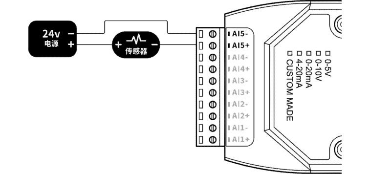
2, 3-wire sensor wiring
Analog voltage/current 3-wire wiring shown
Analog voltage/current 3-wire wiring shown
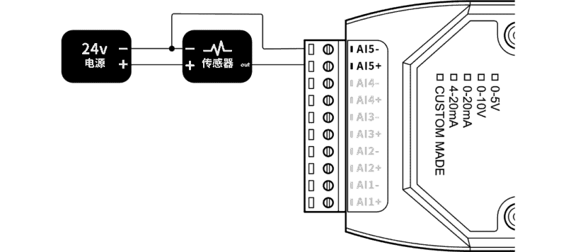
3, 2-wire sensor wiring
Two-wire signaling means that the signal and power wires on the instrument or device add up to only two terminals. Since the FBT Industrial IO analog module channels do not have a power supply, the instrument or device requires an external 24V DC power supply. Analog voltage/current two-wire wiring shown.
Two-wire signaling means that the signal and power wires on the instrument or device add up to only two terminals. Since the FBT Industrial IO analog module channels do not have a power supply, the instrument or device requires an external 24V DC power supply. Analog voltage/current two-wire wiring shown.
Related products
data transmission
¥272 – ¥308
This product has multiple variants. The options may be chosen on the product page


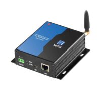
serial port server
Industrial WiFi Serial Server RS232/485/422 to WiFi Dual Serial Ethernet Transmission WE-W220
¥235
temperature sensor
NB-IOT Wireless Temperature and Humidity Sensor LCD Display Battery Powered WE-NBTHAD
¥580