


-
×
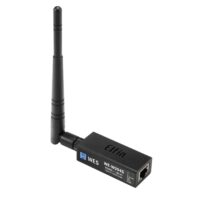
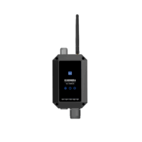 无线网络基站 WE-RWN300 (test)
1 × ¥980
无线网络基站 WE-RWN300 (test)
1 × ¥980

Product Features
- Industrial grade core for stable and reliable performance
- Chip main frequency up to 320M
- Power supply reverse connection prevention design
- 5V-36V wide voltage design, suitable for various industrial control sites
- Instantaneous high current protection against lightning strikes, power switching
- Electrostatic ESD protection against dust and arc damage
- Watchdog function for 24-hour stable operation
- Firmware upgrades are performed over the network
- Provide SDK support
- Working temperature: -45 degrees to 85 degrees
¥59
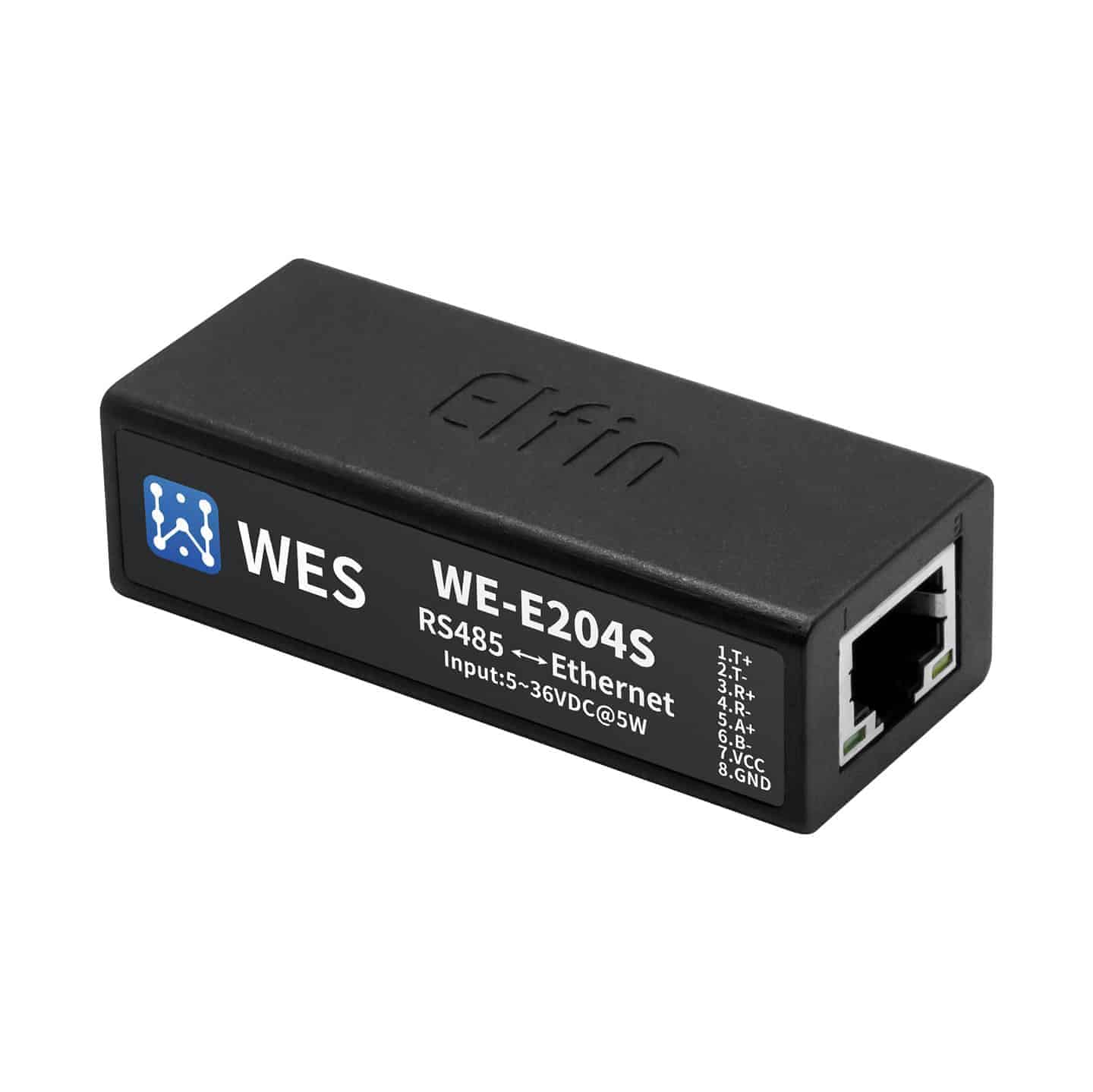
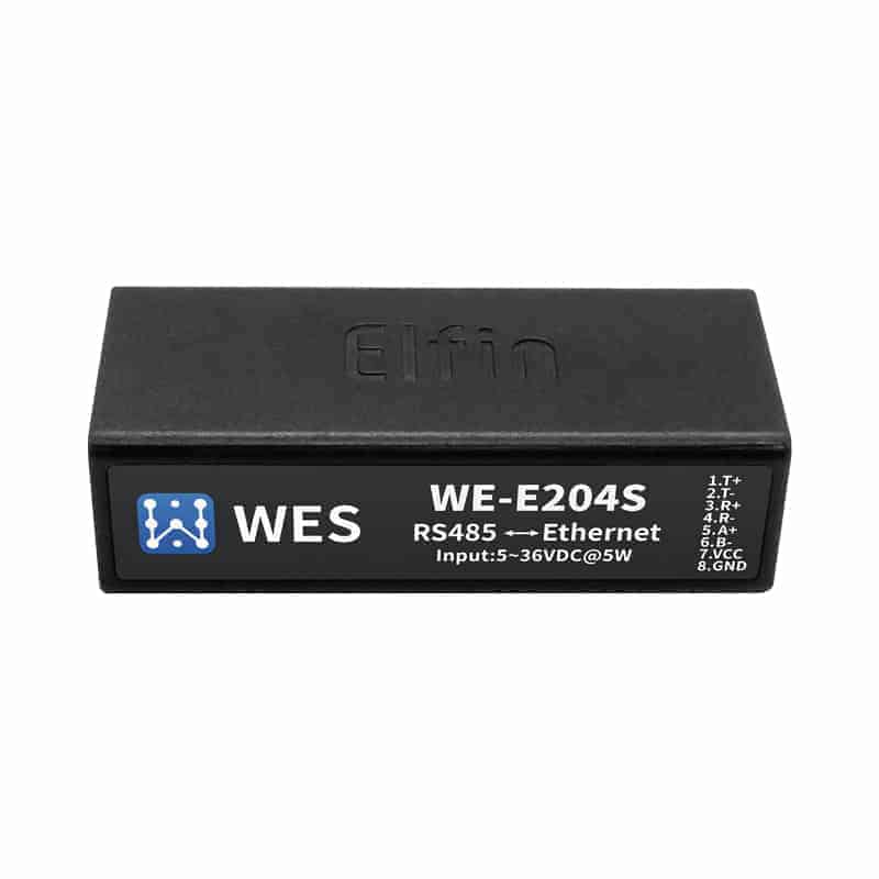
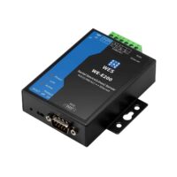
Product Overview
WE-E202S/E204S Serial Server provides a protocol conversion product between RS232/RS485 and TCP/IP to meet the solution of serial to Ethernet data transmission channel, this product integrates Ethernet hardware protocols such as MAC and TCP/IP protocol stack, memory management, 10/100M Ethernet transceiver, high-speed serial port, The product integrates TCP/IP protocol stack, memory management, 10/100M Ethernet transceiver, high-speed serial port, RS232 or RS485 and other rich hardware interfaces, and based on the FreeRTOS operating system, the product includes a web page, which can be easily used for remote configuration, monitoring and debugging.
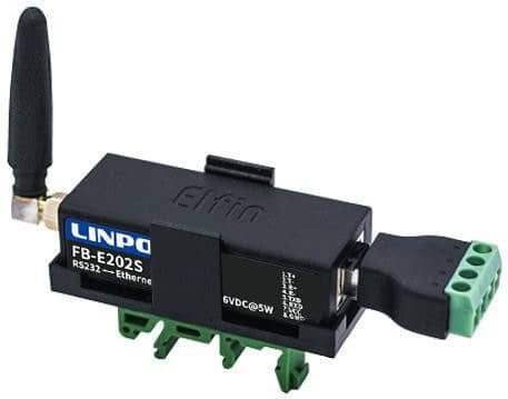
The WE-E202S/E204S serial servers utilize a highly integrated hardware and software platform.
FB-E202S/E204S Serial Server Dimensions 61mm x 26mm x 17.8mm
Application Areas
Serial servers connect serial devices to the Internet and transmit serial data in compliance with the TCP/IP protocol.
- Remote equipment monitoring
- Production Asset Tracking and Monitoring
- Security
- Industrial Sensors and Controllers
- Healthcare equipment
- ATM equipment
- Data acquisition equipment
- UPS Power Management Devices
- Telecommunications equipment
specification
| categorization | parameters |
| System Information | |
| Processor/Main Frequency | Cortex-M3/96MHz |
| Flash/SDRAM | 2MB/128KB |
| operating system | FreeRTOS |
| Ethernet interface | |
| ports | 1 |
| interface standard | 10/100M Base-T auto-negotiation |
| Network Transformer | integrated (as in integrated circuit) |
| network protocol | IP, TCP, UDP, DHCP, DNS, HTTP Server/Client, ARP, AutoIP, ICMP, Telnet, NTP, Modbus TCP, TLS 1.2 |
| security protocol | AES 128Bit DES3 |
| serial port (computing) | |
| port number | FB-E202S: 1 RS232 FB-E204S: 1 RS485 |
| data bit | 5, 6, 7, 8 |
| stop bit | 1, 2 |
| check digit | None, Even, Odd |
| baud | TTL: 600 bps~460800bps |
| flow control | no-flow control |
| Software Xon/ Xoff Flow Control | |
| hardware | |
| Web Configuration | Http Web Configuration |
| Customizable and customizable Http pages | |
| Configuration | Web page Cli commands XML file import Telnet Configuration IOTService Configuration Software UART Quick Configuration |
| Firmware Upgrade | Web, IOTService Tools |
| Basic parameters | |
| sizes | 61 x 26 x 17.8 mm |
| operating temperature | -40 ~ 85°C |
| preservation environment | -45 ~ 105°C, 5 ~ 95% RH (no condensation) |
| Input Voltage | FB-E202S, FB-E204S: 5 to 18VDC |
| Operating Current | ~100mA |
| power wastage | <400mW |
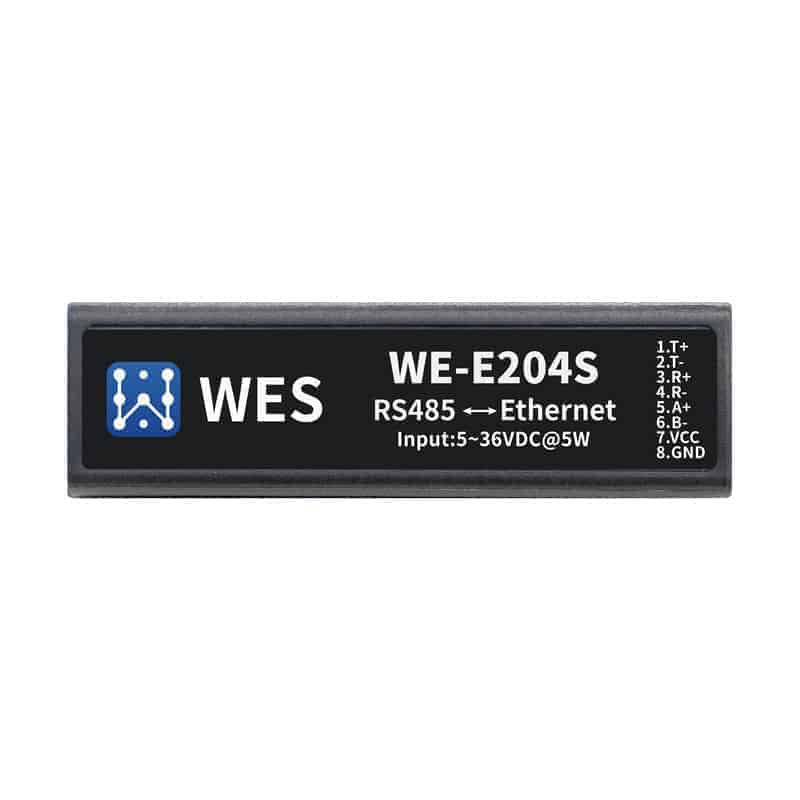
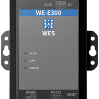
blueprint
Overall dimensions

interface definition

| pin | descriptive | Internet name | Signal Type | clarification |
| 1 | Ethernet output+ | TX+ | O | Connects to standard RJ45 network cable PIN1 |
| 2 | Ethernet Output - | TX- | O | Connects to standard RJ45 network cable PIN2 |
| 3 | Ethernet input + | RX+ | I | Connects to standard RJ45 network cable PIN3 |
| 4 | Ethernet Input - | RX- | I | Connects to standard RJ45 network cable PIN6 |
| 5 | Communication Serial Port TX | RS485_A+ | IO | RS485 Level A+ Phase |
| 6 | Communication serial port RX | RS485_B- | IO | RS485 Level B-Phase |
| 7 | Power supply input | VCC | Power | 5 to 18VDC |
| pin | descriptive | Internet name | Signal Type | clarification |
| 8 | POWER GROUND | GND | Power | |
| greenerstatus light | Normally lit: the module completes startup and begins normal operation. | |||
| 9 | net (computing) | O | 0.3 sec. off, 3 sec. on: positive Ethernet connection | |
| Regular.
Off for 0.3 sec, on for 0.3 sec: Ethernet connection abnormal. |
||||
| Extinction: no data interaction | ||||
| 10 | amber
Data transmission indicator |
Active | O | 0.3 sec. off, 0.9 sec. on: Serial port output data
0.3 sec. off, 0.3 sec. on: Serial port receives data |
| Standing light: two-way send and receive. |
take note of
RS485 lead wire are A (data +) and B (data -), and equipment RS485 connection A (+) connected to the A (+), B (-) connected to the B (-), interference in the case of serious recommended to connect the GND together.
This product can be used with 32 terminal 485 devices, with a maximum communication distance of 1200 meters. The maximum communication distance is 1200 m. The 485 termination resistor is 120 ohms, which is usually necessary for wiring over 300 meters. Note that when wiring, A+ and B- must be a pair of twisted pairs hinged together to minimize signal interference.
RJ45 connection


Models and accessories
Interface Conversion Cables


You can make your own cables according to the schematic
Guides & Brackets

Fixed bracket

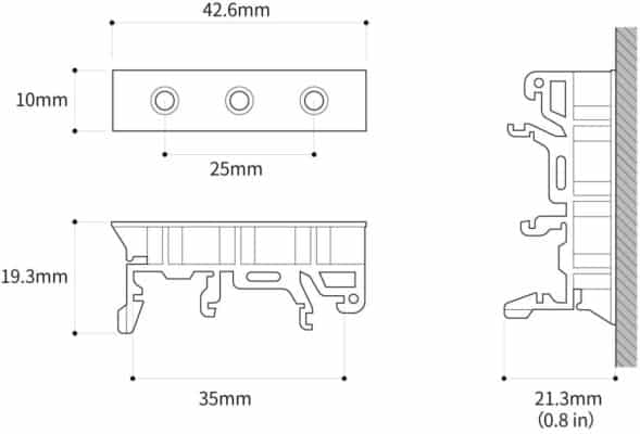
Dimensional drawing of guide rail bracket

Bracket Installation Schematic

User Installation Diagram

caveat
Attention to the use of the product
battery capacity
Local regulations
Outdoor temperature and humidity
Resource support
WE-E204S User's Manual
Installation Manual
instruction manual
Code (if any)
Documentation
External resources
Chip Specification DATASHEET
Related products

data acquisition
Industrial 16-channel digital input RS485 data wireless acquisition module WE-TDI16RM
¥350

Pressure sensors
¥601 – ¥780
This product has multiple variants. The options may be chosen on the product page
¥69


serial port server
WiFi serial server RS232 to WiFi small size networking communication module device WE-W202S
¥69
¥268