


Product Features
- Supports the latest WIFI6 wireless protocol
- Supports low power consumption mode
- Compact size for easy integration and installation
- Cost-effective and more competitive in the market
¥22 – ¥25
Product Overview
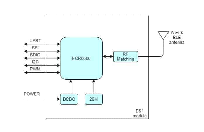
- ES1 is an IOT module that supports WiFi6 and BLE5.1 wireless protocols. It is designed based on ESWIN's ECR6600 chip with integrated RF matching circuit, antenna, clock circuit and power supply circuit. Users can integrate the module into the motherboard, providing UART/SPI/SDIO and other communication interfaces with WIFI6 protocol conversion, conveniently realizing the wireless networking function of end products; it has powerful performance, supporting the latest 802.11ax protocol, compared to the traditional 802.11n/ac protocol, it has a wider coverage, higher rate, and lower power consumption; built-in 240Mhz high-performance MCU, can be widely used in smart home, industrial control, video transmission, voice processing and other applications.
- ES1 module supports freeRTOS operating system, which is convenient for customers' secondary development. The module supports low-power mode, which is suitable for applications with stringent power consumption requirements. The module's ultra-small size of 18*12.5mm makes it easy to be integrated into products with smaller dimensions.
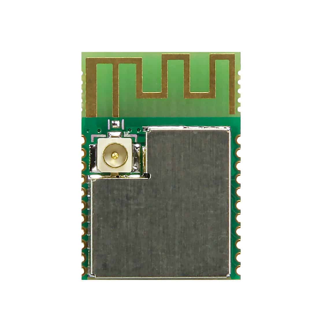
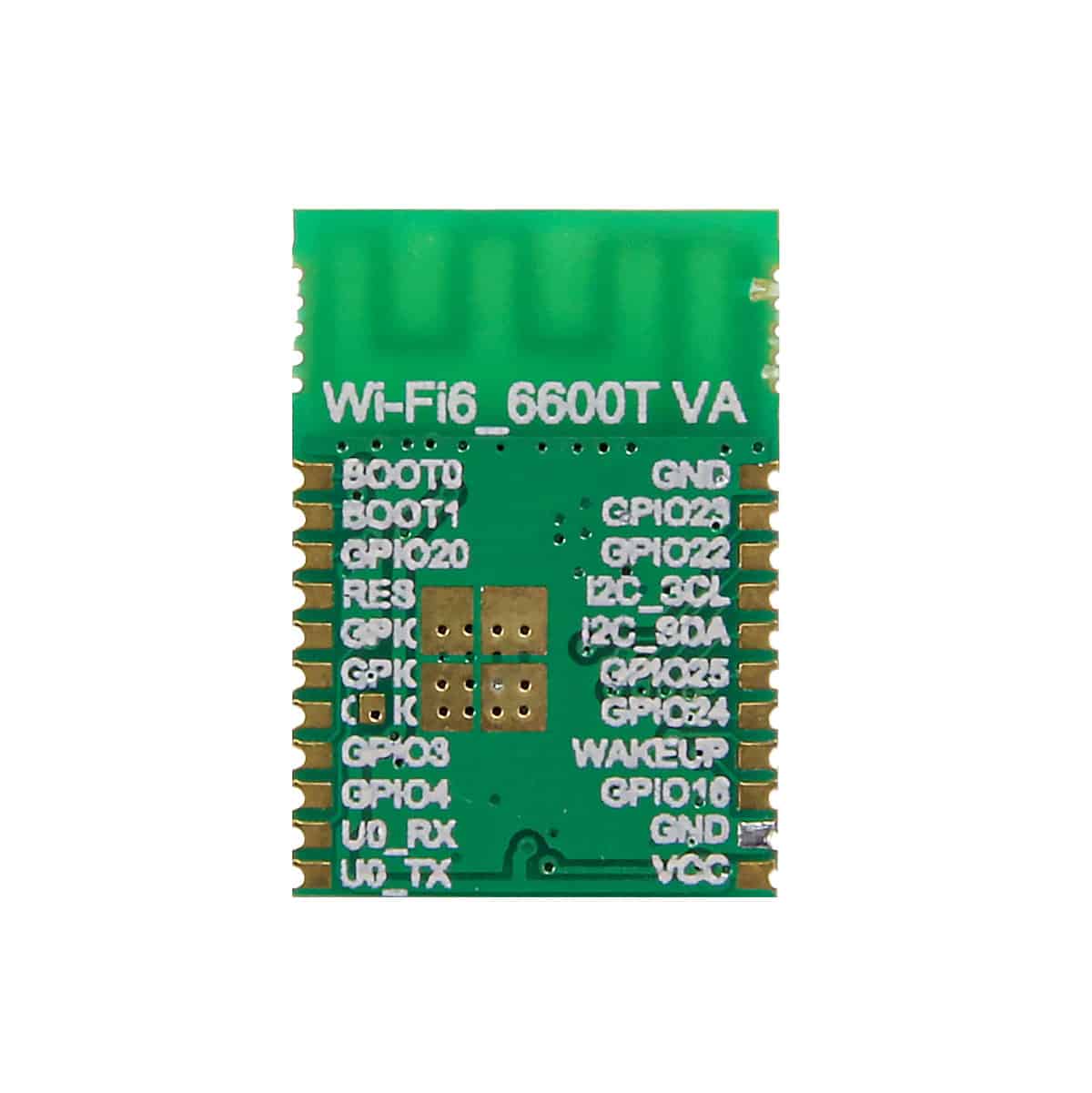
- In order to facilitate customers to use in different scenarios, ES1 module provides two versions of antenna interface, one IPEX interface ES1-IPEX, which allows users to extend the antenna to a suitable position through the cable, and the other ES1-ANT with on-board antenna, which saves the cost of external antenna.
| Weight | 500 g |
|---|---|
| Dimensions | 15 × 12 × 5 mm |
| model number | ES1-IPEX (IPEX antenna interface), ES1-ANT (on-board antenna) |
Product Size


Main parameters

Electrical parameters
Module power supply
ES1 supports 3.3V single power supply, and the module internally adopts DCDC mode to transform the 1.0V and 0.8V voltages required by the chip. The DCDC mode can effectively reduce the power consumption of the module, minimize the heat generation of the module and prolong the service life of the battery.
A 10uF capacitor and a 100nF capacitor decoupling need to be placed near the input power inlet of the ES1 module (PIN11 and PIN12 pins).
reset pin
The reset pin of ES1 is on PIN19 of the module, the reset signal is active low, after the module is powered up, please keep the reset signal low for 100us and then pull the reset signal high.
burner interface
The ES1 module uses the UART0 (PIN12, PIN13) interface to burn the program. The default baud rate of UART0 is 115200, and the RDtool software provided by the chip manufacturer is used for burning.
In order for the module to enter burn mode, it is necessary to connect the RESET of the ES1 module to the RTS pin of the computer's serial port, so it is necessary to select a serial-to-USB chip or module that supports the RTS pin to connect to the computer.
AT command interface
The UART1 (PIN17, PIN18) pins of the ES1 module are AT command interfaces, and the default baud rate of UART1 is 115200. You can input AT commands to configure the module or transmit data through the UART1 port.
For AT commands, refer to the AT Command Manual Documentation.
Technical Information


Related products

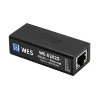


serial port server
WiFi serial server RS232 to WiFi small size networking communication module device WE-W202S
¥69
