


popularization of knowledge
UWB Indoor Positioning Based on IEEE 802.15.4a Standard Details
发表于 知识科普 |TOA,TDOA,RSSI Positioning Technology Details

UWB Technology Overview
Ultra Wide Band (UWB) technology is a wireless communication technology that covers a wide spectrum of frequencies by transmitting short pulse signals. It is capable of providing high data rates and very high positioning accuracy over short distances. Unlike conventional narrowband systems, UWB offers greater immunity to interference and higher efficiency in bandwidth utilization.
IEEE 802.15.4a standard
The IEEE 802.15.4a standard is designed to enhance the use of UWB technology in wireless personal area networks (WPANs). It provides greater accuracy and reliability through improved ranging and localization capabilities, making it particularly suitable for indoor positioning applications.
Indoor Positioning Principle
The core of indoor localization technology is to accurately measure the distance between a target device and a known location.UWB technology uses the following three main ranging methods:
📍 Time of Arrival (TOA):
The TOA measurement method determines the distance by calculating the propagation time of the signal from the transmitter to the receiver. Due to the short pulse and broadband nature of UWB signals, the time of arrival can be precisely measured, resulting in centimeter-level positioning accuracy.
TOA Schematic
illustrate
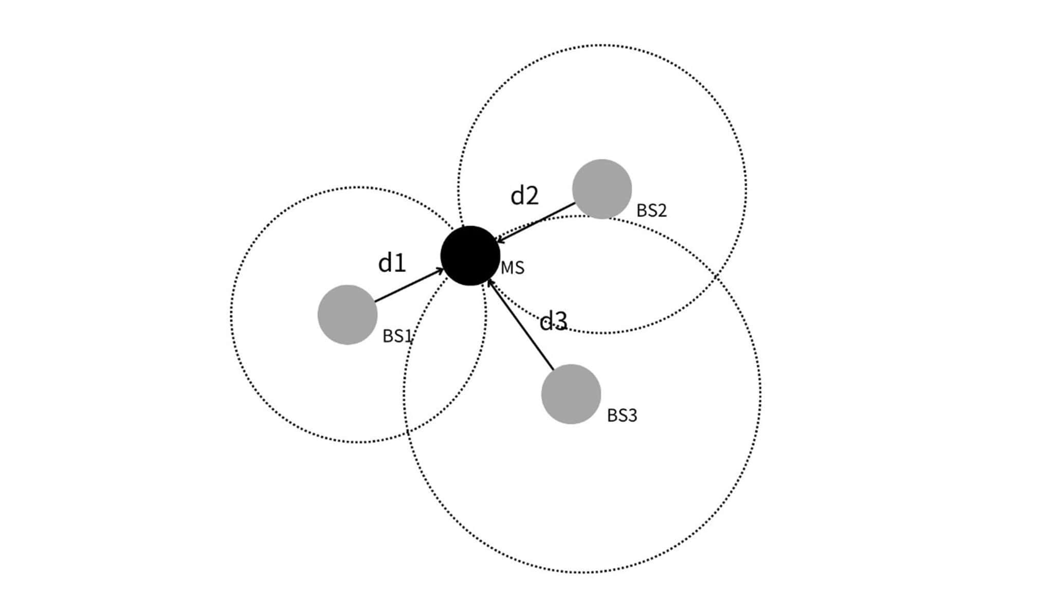
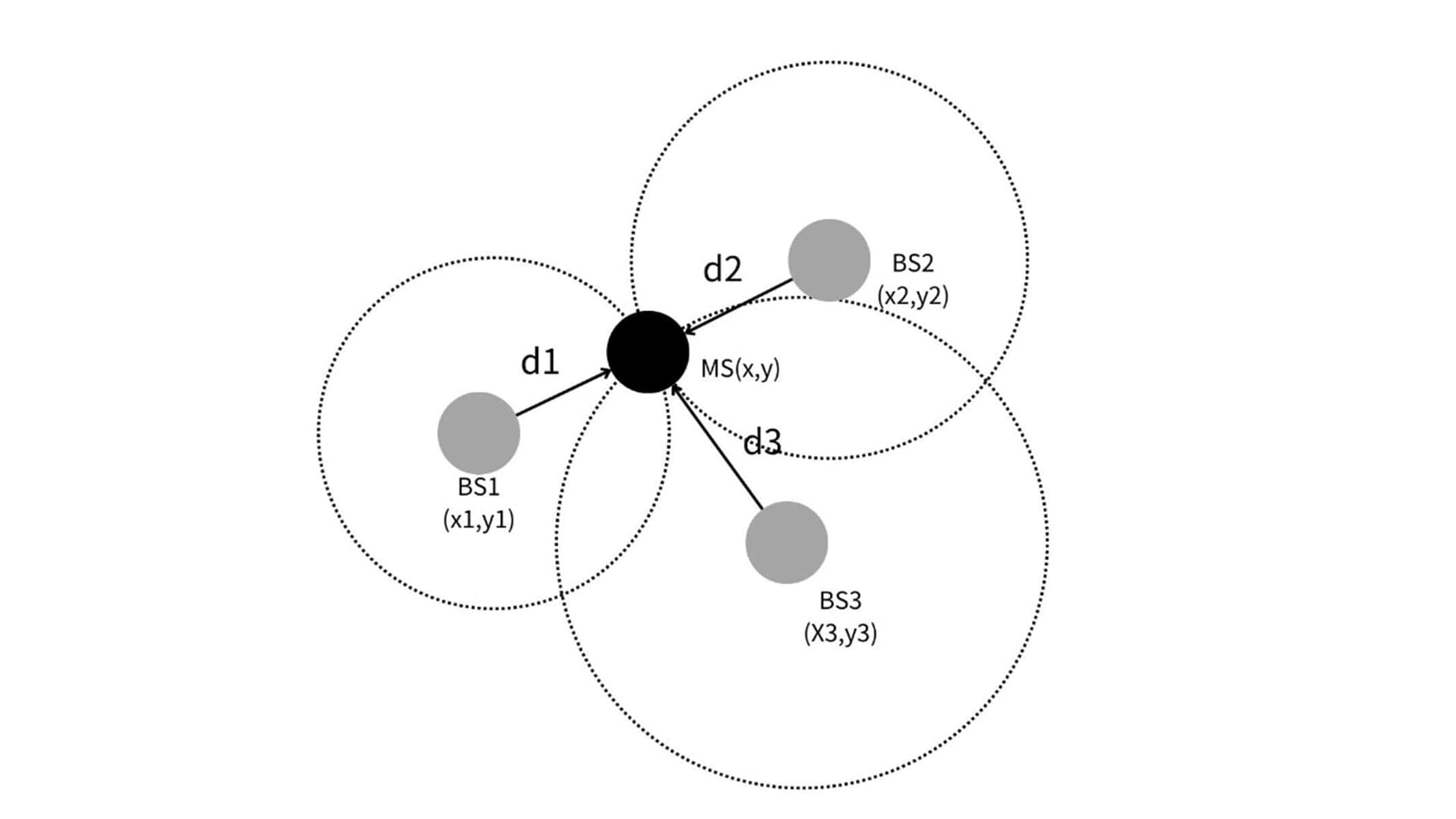
The TOA-based localization computation method is illustrated in Fig. where:
- MS (Mobile Station):Mobile stations (or tags), which need to be located.
- BS1, BS2, BS3:Base station, known location, used to receive signals.
- d1, d2, d3:Distance from the mobile station to each base station.
Positioning Calculation Steps:
Step 1: Signal Transmission and Reception
- The mobile station (MS) transmits UWB signals.
- Three base stations (BS1, BS2, BS3) receive the signal and record the arrival time.
Step 2: Positioning Equation
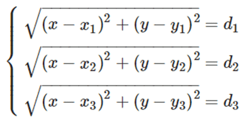
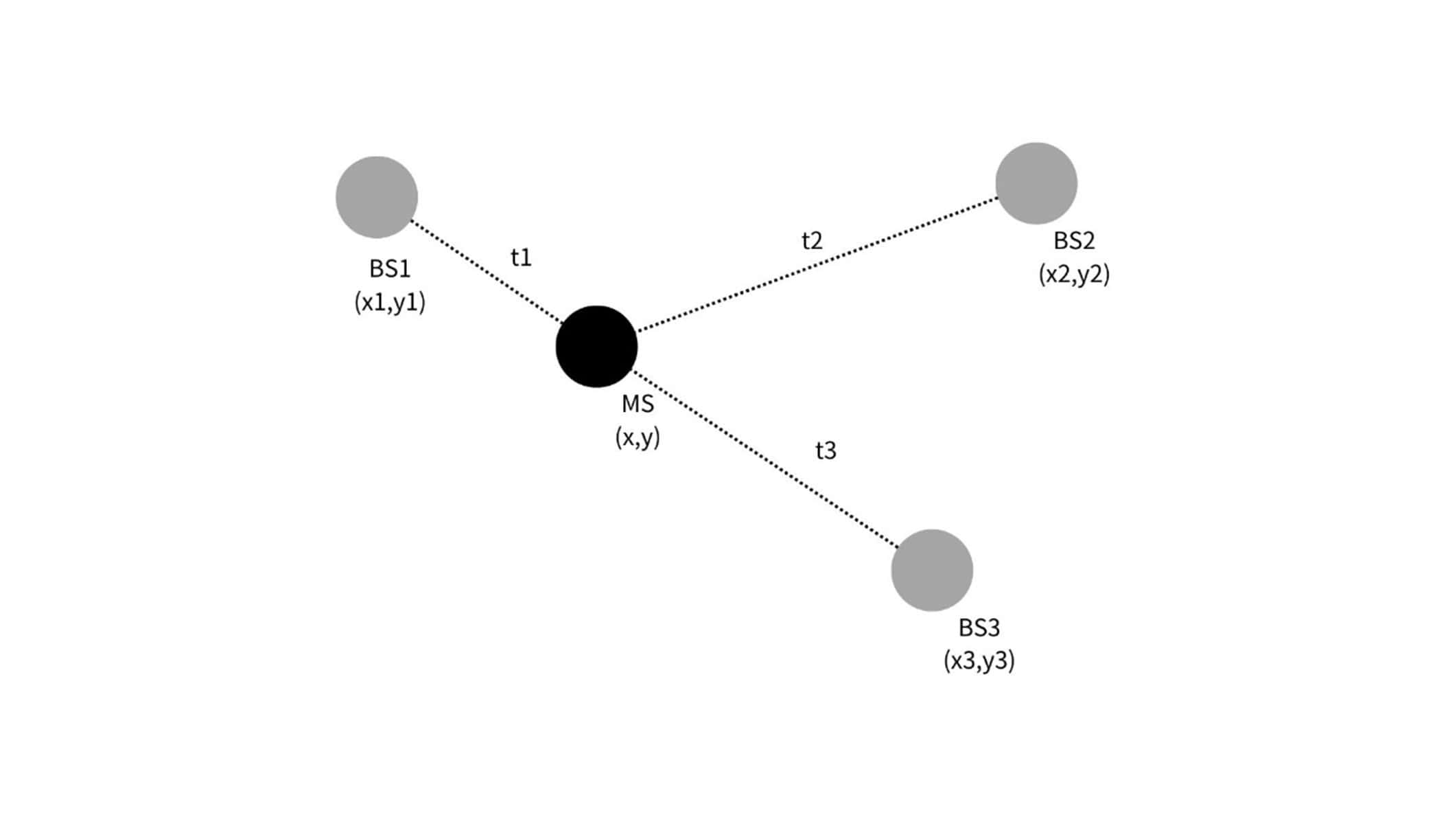
- Assume that the coordinates of the mobile station are (𝑥,𝑦) and the coordinates of the base station 𝐵𝑆𝑖 are (𝑥𝑖,𝑦𝑖).
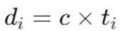
- The product of the propagation time of the signal from the mobile station to each base station tit_iti and the propagation speed of the signal ccc (usually the speed of light) gives the distance from the mobile station to each base station
 These distances satisfy the following equations. These distances satisfy the following equation:
Step Three:
- The coordinates of the mobile station (𝑥,𝑦) can be obtained by solving the above system of equations.
mathematical explanation
The above system of equations represents three circles with each base station as the center and the corresponding distance as the radius. The intersection of these three circles is the location of the mobile station. By solving the system of equations, the location of the mobile station can be precisely determined.
reach a verdict
TOA (Time of Arrival) is another commonly used localization technique that determines a position based on the time it takes for a signal to propagate from the transmitting source to the receiver.TOA directly measures the difference in time between the moment of transmission and the moment of reception of a signal, and thus calculates the distance between the source and the receiver. Since the speed of signal propagation is known (e.g., the speed of radio waves in air is close to the speed of light), the distance can be estimated from this time difference.
The TOA method usually requires very precise clock synchronization, because any error in the time measurement will directly affect the accuracy of the distance calculation. This method is more widely used in open outdoor environments, such as GPS technology is based on the TOA method to achieve global positioning. Compared with TDOA, TOA requires more hardware and clock synchronization, but it can provide very accurate positioning information.
📍 Time Difference of Arrival (TDOA):
TDOA Schematic
summarize
TDOA (Time Difference of Arrival) is a method of localization using the time difference between the arrival of signals at different receivers. Unlike TOA, TDOA does not require synchronization between transmitters and receivers, but only between receivers. This makes TDOA more flexible and practical in practical applications.
TDOA Positioning Principle
The TDOA positioning technique calculates the location of a transmitter by measuring the time difference between the arrival of signals from the transmitter to different receivers. The basic principle is that since signals arrive at different receivers at different times, these time differences can be used to calculate the relative distances between the transmitter and each receiver, and thus determine the location of the transmitter.
step by step
- Signal transmission and reception:
- The transmitter (tag) sends a UWB signal.
- Multiple receivers (base stations) pick up the signal and record the time of arrival. - Calculate the arrival time difference:
- Select a receiver to use as a reference point (usually the closest or strongest signal).
- Calculate the signal arrival time difference between the other receivers and the reference receiver. - Construct the time difference equation:
- Suppose the position of the emitter is (𝑥,𝑦).
At the bottom are the known parameters ⇣
- The locations of base station 1, base station 2, and base station 3 are (𝑥1,𝑦1), (𝑥2,𝑦2), and (𝑥3,𝑦3), respectively.
- The signal arrives at base station 1, base station 2, and base station 3 at 𝑡1, 𝑡2, and 𝑡3, respectively.
- The signal arrival time of the reference base station is 𝑡1 and the signal arrival time difference of the other base stations is Δ𝑡𝑖𝑗 = 𝑡𝑖-𝑡𝑗.
- The signal propagates with a velocity of 𝑐 = 3 × 10⁸ m/s. - Constructing the localization equation:
- Construct the following equations based on the geometric relationships: - Solve for location:
- Solve the above system of equations for the coordinates of the transmitter (𝑥,𝑦).

mathematical explanation
The above system of equations represents the distance differences between the transmitter and each receiver, and the position of the transmitter can be determined by the geometric relationship between these distance differences. This method utilizes the relative time differences between a plurality of receivers to construct a set of nonlinear equations, and by solving these equations, the position of the transmitter can be precisely located.
Benefits and Applications
- Pros:
- No need to synchronize transmitters and receivers: Only synchronized receivers are required, simplifying system implementation.
- High precision: Capable of providing centimeter-level positioning accuracy.
- Robustness: It still performs well in complex environments and is resistant to multi-path interference.
- Application Scenarios:
- Intelligent Logistics and Warehousing: Instantly track the location of items and equipment to optimize logistics and inventory management.
- Medical monitoring: Track the location of patients and equipment to ensure proper resource allocation and patient safety.
- Intelligent Buildings: Controls lighting, air conditioning and security systems, providing personalized services based on the location of people.
- Retail: Analyze customer behavior, optimize product layout, and personalize the shopping experience.
reach a verdict
TDOA positioning technology realizes high-precision positioning by measuring the time difference between signals arriving at different receivers. It eliminates the need for synchronization between transmitters and receivers, simplifying system implementation and making it suitable for a variety of application scenarios that require precise location services. By integrating TDOA technology, enterprises can improve operational efficiency, optimize resource management, and provide a better user experience.
📍 Received Signal Strength (RSS):
RSSI Schematic
summarize
RSSI (Received Signal Strength Indicator) is a technology that utilizes the strength of the received signal for positioning.RSSI positioning technology infers the distance from the transmitter to the receiver by measuring the strength of the wireless signal at the point of reception. Since signal strength is usually inversely proportional to distance, this relationship can be utilized for positioning.
The Basics of RSSI Localization
The RSSI localization technique is based on the following assumptions:
- Wireless signals attenuate during propagation, and the signal strength decreases as the distance increases.
- By measuring the strength of the received signal and combining it with known signal propagation models, the distance between the transmitter and receiver can be deduced.
step by step
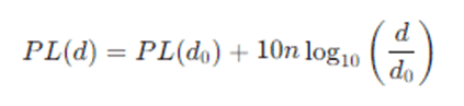
- signal propagation model The propagation of wireless signals in free space can be described by a path loss model, and the common models are the free space path loss model and the logarithmic distance path loss model.
▸ Free-space path loss model::
Among them:
- 𝑃𝐿(𝑑) is the path loss (in dB) at a distance of 𝑑
- 𝑃𝐿(𝑑0) is the path loss at the reference distance 𝑑0
- 𝑛 is the path loss exponent, usually between 2 and 4
- 𝑑 is the distance from the transmitter to the receiver
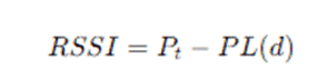
▸ Logarithmic distance path loss modeling:
Among them:
- 𝑅𝑆𝑆𝐼 is the received signal strength (in dBm)
- 𝑃𝑡 is the transmit power (in dBm)
- 𝑃𝐿(𝑑) is the path loss
- Measuring RSSI The receiver receives the wireless signal sent by the transmitter and measures the strength (RSSI value) of the received signal.
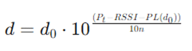
- Distance estimation Based on the measured RSSI values and the known signal propagation model, the distance from the transmitter to the receiver is calculated. Using the free space path loss model, the calculation formula is:
Multi-point and three-sided measurements To improve positioning accuracy, RSSI measurements are often made using multiple receivers. Each receiver calculates the distance to the transmitter based on the measured RSSI value. The position of the transmitter is then calculated by trilateration.
give an example
Suppose there are three receivers (AP1, AP2, AP3) with known coordinates (𝑥1,𝑦1), (𝑥2,𝑦2), and (𝑥3,𝑦3) transmitters whose positions we need to determine.
- Measuring RSSI values
- The RSSI value measured by receiver AP1 is 𝑅𝑆𝑆𝐼1
- The RSSI value measured by receiver AP2 is 𝑅𝑆𝑆𝐼2
- The RSSI value measured by receiver AP3 is 𝑅𝑆𝑆𝐼3 - Estimated distance
- Based on the RSSI values and the signal propagation model, the distance from the transmitter to each receiver 𝑑1, 𝑑2, and 𝑑3 is estimated. - Calculation of position by trilateral measurement
- The position of the transmitter (𝑥,𝑦) is calculated by the following system of equations using trilateral measurements:


By solving these equations, the exact location of the transmitter can be obtained.
Advantages and limitations
- Pros:
- Simple to implement: no complex hardware is required, just a receiver capable of measuring RSSI values.
- Low cost: Positioning can be achieved using existing wireless network equipment.
- Limitations:
- Lower accuracy: Signal strength is easily affected by environmental factors (e.g. walls, obstacles, multipath effect, etc.), resulting in low positioning accuracy.
- Limited scope of application: In complex indoor environments, RSSI values fluctuate greatly, affecting the positioning effect.
application scenario
- Indoor positioning: such as shopping malls, hospitals, warehouses and other places to locate people and equipment.
- IoT: Location monitoring and management of IoT devices.
- Asset Tracking: Immediate tracking and management of critical assets.
reach a verdict
RSSI localization technique estimates the position of the transmitter by measuring the strength of the received signal, which has the advantages of simple implementation and low cost, but also has the limitation of low accuracy. Combined with other positioning techniques, such as TOA and TDOA, the positioning accuracy can be further improved to meet the needs of different application scenarios.
UWB Indoor Positioning System Components
- Transmitter (tag):
- A tag is a small device attached to an object that needs to be located, which periodically transmits a UWB signal. Tags can be mobile, such as mounted on a person or piece of equipment, or fixed, to mark a specific location. - Receiver (base station):
- Base stations are installed at known locations to receive UWB signals from tags. Multiple base stations work together to calculate the location of the tag by measuring the TOA or TDOA of the signal. - Positioning engine:
- The positioning engine is the core module that processes and calculates the data. It receives measurements from the base station, uses a positioning algorithm to calculate the exact location of the tag, and transmits the location information to the user application.
Indoor positioning algorithm
UWB indoor positioning systems use multiple algorithms to improve positioning accuracy and reliability:
- Trilateration:
- The location of the tag is determined by geometric calculations using ranging information from at least three base stations. The trilateral measurement method requires highly accurate TOA or TDOA measurements to provide accurate position estimates. - Kalman Filtering:
- Kalman filtering is a recursive algorithm for processing and predicting the state of dynamic systems. It can effectively reduce measurement noise and improve positioning accuracy. - Particle Filtering:
- Particle filtering is a statistically based algorithm that estimates position by generating multiple possible states (particles) and updating these states based on measurements. It is suitable for systems with nonlinear and non-Gaussian distributions and can provide more robust localization results.
Application Scenarios of UWB Indoor Positioning Technology
- Smart logistics and warehousing:
- UWB technology can instantly track items and equipment in the warehouse, optimizing inventory management and logistics processes and improving operational efficiency. - Medical monitoring:
- Hospitals can utilize UWB positioning technology to track the location of patients, healthcare workers and equipment to ensure proper resource allocation and patient safety. - Intelligent Buildings:
- In smart buildings, UWB positioning technology can be used to control lighting, air conditioning and security systems, providing personalized services based on the location of people. - Retail:
- Retailers can analyze customer behavior, optimize merchandise layout, and provide a personalized shopping experience through UWB positioning technology.
reach a verdict
UWB indoor positioning technology using the IEEE 802.15.4a standard provides a highly accurate, low-power and robust positioning solution. With accurate ranging methods and advanced positioning algorithms, UWB technology delivers outstanding performance in a wide range of application scenarios. By integrating UWB indoor positioning technology, enterprises can improve operational efficiency, optimize resource management, and provide a better user experience.

Content Reviewer:Mick Weng