


RS485 Data Communication Protocol
(i) Overview of the agreement
The RS485 protocol adopts a question-and-answer polling mechanism, in which the controller queries the read tag data to the reader and the reader reports the read tag data to the controller. The controller can decide the polling strategy according to the actual situation, such as a time to check all the data on a reader, or each time to check a fixed number of data as soon as possible after the next reader, to ensure that the polling of real-time.
(ii) Description of the agreement
1Message Format
| 1 | 1 | 1 | 1 | N | 2 |
| device address | Version (0) | command | data length | Data content | CRC check |
Device Address: the RS485 address of the reader that is queried or responded to.
Version number: Used for controller and reader version compatibility (current version number is 0).
Command: used to indicate what message this is.
Data length:The length of the data content contained in the message.
Data content:The specifics of the data contained in the messageThe
CRC checksum: CRC16 checksum algorithm. It is the checksum value of all previous data in the message.
message command
| command | (be) worth | orientations | clarification |
| consult (a document etc) | 1 | Controller --> Card Reader | The controller queries the reader for data |
| responsive | 2 | Card Reader --> Controller | Reader feeds data back to the controller |
| Inquiry + Call | 3 | Controller --> Card Reader | The controller queries the reader for data and commands the reader to initiate a call to the specified tag. |
2, query message (0x01)
The "content data" of the message is 1 byte, which holds the maximum number of tags that the reader is allowed to report for this query.
Examples:
If "Content Data" is 10, the reader can only report 0~10 tag event data after receiving this query message. The controller receives less than 10 data, then the reader has sent all the data. Controller received 10 data, the reader may still have not sent the data, at this time, the controller is to continue to query, or polling the next reader, the advantages and disadvantages of each, decided by the controller autonomy.
Message example:
01 00 01 01 08 56 48

3, response message (0x02)
The "content data" of the message is the actual content of the tag event reported by the reader. The details are as follows:

The "Base Station Status Data" occupies 1 byte in length and is used to indicate the status of the base station (card reader).
State 0: card reader is working normally
Status 1: Antenna Failure (no reader antenna connected or reader antenna failed)
State 2: Reader congestion (too many tags beyond the reader's processing capacity).
"Tag event data" consists of 1 byte of the number of tag events and the corresponding tag event data. Each tag event data consists of "card number", "attribute", "extended data" and "RSSI value" fields. Each tag event data consists of "Card Number", "Attributes", "Extended Data" and "RSSI Value" fields.
(1) Card number. 4 bytes, the number of the tag, followed by all the information for that tag.
(2) Attributes. 1 byte, stores label type, undervoltage flag, extended data length, etc.

Bit 0 Undervoltage flag. 1: Undervoltage 0: Normal
Bits 1-3 Label Type. 0: Plain Label 1: Motion Detection Label 7: Empty Label (Note 1)
Bit 4 Motion Flag. This bit is only valid for motion detection tags. 0: tag at rest 1: tag in motion
Bits 5-7 Extended data length. If necessary, the tag can upload some extended data (e.g. humidity, moisture, etc. data), the extended data area follows the attribute byte and can be 0-7 bytes in length.
Note 1: Empty tag refers to the active tag attachment does not have any electronic tags, in order to indicate to the controller that the active tag is working properly, and every 3 seconds to the controller to send empty tag information. If the controller does not receive real tag information or empty tag information for a long time, it means that the reading antenna is working faulty.
(3) Extended data. 0-7 bytes, the length of the extended data is stated in the attribute byte, which can carry some tag-specific data, such as temperature, temperature and other data. There can be up to 7 bytes or none.
(4) RSSI value. 1 byte, the read card antenna receives the tag data wireless signal strength value, through the signal strength value can be converted to the tag from the read card antenna distance.
Message example:
01 00 02 0E 00 02 00 1B 81 7A 00 AB 00 1B 81 7B 00 AA 06 B2

4Inquiry+Call control messages (0x03)
The message sends a call control command to the specified tag while querying the read data, so that the tag starts or stops glowing and sounding.
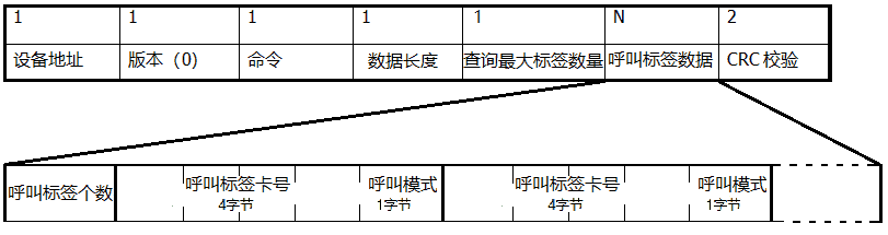
Call Mode:
0: Lights on (no sound)
1: Lights on (audible)
255: Cessation of luminescence and sound
Message example: 01 00 03 0C 08 02 00 1B 81 7A 01 00 1B 81 7B 01 7E 9F
