


Programmatic background
With the development of Internet of Things technology, wireless sensing and wireless digital transmission applications will become more and more widespread. Utilizing micropower networking technology to build advanced grid information architecture is also a major application direction of power automation now; due to the power limitation of ISM frequency band, the transmission distance is limited;Some of the following challenges are encountered when using pure wireless networking in high-rise buildings:
- latency of multi-hop networking.
- codeblind spot(math.) genus
- Energy saving at the nodesThe
In order to better solve the above reasons and some transmission problems encountered in the actual use of the actual customers, we propose a "wired + wireless" hybrid networking method based on our original wired networking bus LZBUS.
LZBUS Overview
LZBUS single bus for long-distance one-master-multiple-slave single-wire transmission bus, by the LZBUS bus communication system can be called LZBUS system, LZBUS system consists of a host and a number of nodes, cable thickness is not the same as the same communication distance is not the same, 1 square mm cable communication distance of up to 1,500 meters or more.
The external wiring of the LZBUS single bus consists of the power line VBUS, the signal line S, and the ground line GND. in the case of low system bus load currents (<2A), the nodes can take power on the bus, i.e., only two wires (GND, S) are needed to communicate, and the nodes can also pass through a bridge stack to make polarity-independent communication, i.e., S, GND can be polarity-independent.
If the system load current is large, you can use the three-wire system, the load current of the entire system can be done more than 10A, so that each node does not have to supply power individually, and it is convenient for engineering wiring.
The system schematic is as follows::
The LZBUS system adopts a master-multi-slave method, and collects the data of each node or controls the switching output of the nodes by the host's searching for the nodes in a round-robin manner. When collecting data, the LZBUS host can collect data from up to 16 nodes with neighboring logical addresses in one frame of command. However, when the system uses two-wire communication, it is recommended to collect node data from up to four neighboring logical addresses at a time.
Wired bus LZBUS+wireless based digital transmission network solution
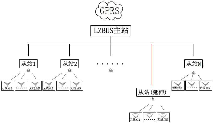
schematic diagram
Program realization principle
The whole system consists of GPRS, LZBUS bus (including master and slave), and wireless nodes;
LZBUS communicates with GPRS through the serial port, the master station communicates with each slave station through the two-wire and each slave station is hooked up to a wireless digital transmission module, and communicates with the wireless nodes governed by this slave station through the wireless module; each slave station can communicate with the wireless nodes governed by the address identification method;
If there is a communication overlap area between the wireless nodes governed by two neighboring slaves, the wireless nodes between different slaves can be set to operate at different frequencies; in this way, kind of even if the neighboring slaves launch queries to the governed module at the same time, no wireless conflict situation will occur.
Content review.