


popularization of knowledge
[Internet of Things Communication Technology]--Radio Frequency Technology
发表于 知识科普 |summarize
Radio frequency (RF) is the rate of oscillation of an alternating current, voltage, magnetic, electric, electromagnetic field electrical or mechanical system at frequencies ranging from about 20 kHz to about 300 GHz. Through the use of antennas and transmitters, RF can be used for various types of wireless broadcasting and communications. InIoT wireless communicationThis article briefly describes some of the concepts of RF technology, which is widely used in various RF technologies.
ISM radio frequency band
The ISM radio bands are internationally recognized for industrial ((Industrial)Science (Scientific)and medical care (see annex I).MThe ISM bands are a portion of the radio spectrum reserved for ISM purposes and do not include telecommunications applications. Typically, communications equipment operating in the ISM bands must be able to withstand any interference generated by ISM applications, and users are not protected by regulation for the operation of ISM equipment in these bands. The fastest growing use in recent years has been in short-range, low-power wireless communication systems, as these bands are often approved for such devices and can be used without government licenses that would otherwise be necessary for transmitters; ISM frequencies are often chosen for this purpose because they already must tolerate interference problems. Cordless phones, Bluetooth devices, near-field communication (NFC) devices, garage door openers, baby monitors, and wireless computer networks (Wi-Fi) may all use ISM frequencies, although these low-power transmitters are not considered ISM devices.


RF Name Explanation
Relationship between frequency and wavelength
The unit of measurement of radio frequency is hertz (Hz), which indicates the number of cycles per second when a radio wave has been transmitted. One hertz equals one cycle per second.
Example.
a. Frequency - number of cycles per second (Hz) - e.g. 2MHz
b. Period - the duration of the completion of a cycle.
c. Wavelength - the distance at which the waveform repeats itself

RF measurement unit dB
dB: decibel, the logarithmic (equal to 10 times) ratio of the difference between two values. Master sites use dB to measure the ratio of transmitted signal energy to reflected signal energy. A common rule of thumb is to double the power and increase it by 3 dB, and halve the power and decrease it by 3 dB.
If 0 dBm represents 1 mW; 10dB = 0.01W ; 20dBm = 0.1W ; 30dBm = 1W

If the power of the carrier (reference signal) is C = 0.1 mW and the power of the noise signal is S = 10 μW.
The reference signal power expressed in decibels is:

The noise power expressed in decibels is:
dBc (decibels relative to the carrier) is the power ratio of the signal to the carrier signal, expressed in decibels.If this transmitter outputs a maximum of 600W/57.78dBm, the harmonics will be no greater than 60mW/17.78dBm!
Why 50 ohms is the most common standard impedance for cable and antenna work
Why is it that in many RF systems or components a 50 ohm impedance is often used (sometimes this value is even the default value of the PCB) , why not 60 or 70 ohms? How is this value determined and what is the meaning behind it?
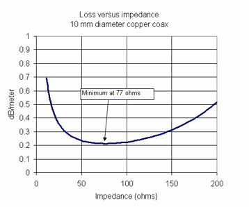
There are two characteristics that affect the transmission of RF signals, transmission power and loss. We expect that wireless signals can be transmitted farther in the case of low loss, in 1929, Bell Labs did a lot of experiments, and ultimately found that in line with this high-power transmission, loss of coaxial cable with its characteristic impedance are 30 ohms and 77 ohms. Among them, 30 ohm coaxial cable can transmit the maximum power, 77 ohm coaxial cable transmission signal loss is the smallest. 30 ohm and 77 ohm arithmetic mean value is 53.5 ohm, 30 ohm and 77 ohm geometric mean value is 48 ohm.

Impedance (Impedance)
In a DC circuit, the resistance to current is simply called resistance. In an AC circuit, the resistance is called impedance. That is, impedance (measured in ohms) is the effective resistance to the flow of current around a circuit that contains both AC resistance and AC reactance. Impedance has two parts, "real" and "imaginary".
Real impedance - electrical energy is converted to heat (resistance), reducing only the signal amplitude.
The actual power will depend on the phase between V and I: the
P = VIcos(ɵ) and ɵ=0 -- P = VI


Imaginary impedance - electrical energy temporarily stored in an electric field (capacitor) or magnetic field (inductor).
Current lags 90° behind voltage


Voltage offset 90° from current


Linear and nonlinear
A linear circuit is a circuit in which the parameters of the circuit (resistance, inductance, capacitance, waveform, frequency, etc.) are constant. In other words, circuits whose parameters do not vary with current and voltage are called linear circuits. Examples include: resistors and resistive circuits, inductors and inductive circuits, capacitors and capacitive circuits.
A nonlinear circuit is a circuit whose parameters vary with current and voltage. In other words, a circuit whose circuit parameters (resistance, inductance, capacitance, waveform, frequency, etc.) are not constant is called a nonlinear circuit. For example, diodes, transistors, transformers, iron cores, inductors (when the core is saturated), any circuit consisting only of an ideal diode, transistors, transformers, iron core inductors are called nonlinear circuits.

Fundamental and Harmonic
Fundamental Frequency: The main frequency (generator frequency); Harmonic Frequency: When any input frequency signal is applied to a nonlinear device, it will produce unwanted frequencies in addition to the input signal. If this excess frequency is an integer multiple of the input frequency, it is called a harmonic.

Harmonic frequencies are integral multiples of the fundamental frequency, and according to the French mathematician Fourier (M. Fourier) the analytical principle proves that any repeating waveform can be decomposed into sinusoidal components containing the fundamental frequency and a series of harmonics that are multiples of the fundamental. For example, given a 50 Hz fundamental waveform, this means that the second harmonic frequency is 100 Hz (2 x 50 Hz Hz), i.e., the third harmonic may be 150 Hz (3 x 50 Hz Hz), the fifth is 250 Hz, the seventh is 350 Hz, and so forth.
Harmonics are the result of nonlinear loads that convert AC line voltage to DC. Harmonics flow into the power system due to nonlinear electronic switching devicesSome examples of nonlinear electronic components are:Diodes, transistors, iron core inductors, and transformers (when the iron core is saturated)Nonlinear electronic circuits that operate in a nonlinear manner are mixers, modulators, rectifiers, radio receiver detectors, and digital logic circuits.
bandwidths
Bandwidth is defined as the difference between the higher and lower frequency components of a signal. Thus, it specifies the amount of data transmitted per second.


Related resources
Content review.