


summarize
Serial communication is the most versatile in the IoT worldcommunications interfaceAs opposed to the serial port, the parallel port is literally similar to a serial port where we talk, one word at a time, whereas the parallel port is similar to an image where we can receive the entire picture at once. In computers, the parallel port can transmit information through 8 data lines at a time simultaneously; while the serial port can only transmit information and data through one line. Therefore, theoretically, parallel port communication is significantly higher than serial port communication.
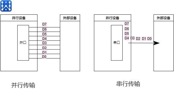
But in reality, why use the serial port of the device more, there are several reasons, one is, although the parallel port at the same time can transmit 8-way or more data, but these data channels between each other high-frequency electromagnetic interference, very easy to error and affect the speed of transmission; on the contrary, the serial port communication does not interfere with the transmission error to re-send again on the second parallel port communication is very much occupied by the hardware pins resources. So the serial hard disk SATA1.0 interface speed can reach 150MB/s, SATA 2.0 up to 300MB/s, 3.0 can be increased to 600MB/s; and parallel ATA can only reach a maximum of 13MB/s. The main reason is that high-frequency data transmission. The main reason is that in the high-frequency data transmission process of high-frequency interference affects the speed of parallel transmission.
Data communication, that is, data through the hardware or software line connection channel, in accordance with certain rules of communication protocols, the formation of data flow from one side to the other. Computers and terminals, sensors need to communicate with each other, commonly used serial communication standards includeRS-232,RS485respond in singingRS422The

Classification according to transmission direction
full duplex
Similar to a highway with 4 lanes in both directions, allowing data to be transmitted in both directions at the same time. Requires the need for separate receivers and transmitters.
half-duplex
Similar to the signs in a traffic road, one road will be opened for traffic depending on the actual congestion; at other moments, only the reverse direction will be allowed. Serial full duplex allows data to be transmitted in both directions. However, at a certain point in time, only one direction is allowed; it does not require separate receivers and transmitters, which can be combined to use a single port.
simplex
In terms of road traffic is the meaning of a one-way street, the meaning of serial port simplex is the same, as the name suggests, simplex is data can only be transmitted in one direction.
Classification by communication method
synchronous communication
With clock-synchronized signal transmission, a signal line is used above the transceiver device to transmit signals, and the two sides coordinate and synchronize data driven by the clock signal. For example, communication usually both sides will be unified provisions in the clock signal on the rising edge or falling edge of the data line for data sampling. Synchronized signals transmit more effective data, but a problem can also arise, synchronized signals require a small error in the clock frequency.
asynchronous communication
Asynchronous communication does not use clock signals for data synchronization, but directly intersperses some signal bits used for synchronization in the data signal, or packages the subject data and transmits the data in the format of data frames. Communication also requires both parties to statute the data transfer rate (that is, baud rate) and so on for better synchronization. Commonly used baud rates are 4800bps, 9600bps, 115200bps and so on.
Classification according to level criteria
TTL standard
TTL means Transistor-Transistor Logic (Transistor-Transistor Logic) power supply operating voltage is 5V, so the level of TTL is based on the power supply voltage of 5V; TTL level logic provides that for the output circuit: the voltage is greater than or equal to (≥) 2.4V is logic 1; the voltage is less than or equal to (≤) 0.4V is logic 0; for the input circuit: voltage greater than or equal to (≥) 2.0V is logic 1; voltage less than or equal to (≤) 0.8V is logic 0.
RS-232 standard
RS-232 level in order to increase the long-distance transmission and anti-interference ability of serial communication, it uses -15V to indicate logic 1, +15V to indicate logic 0.
Several parameters for serial communications
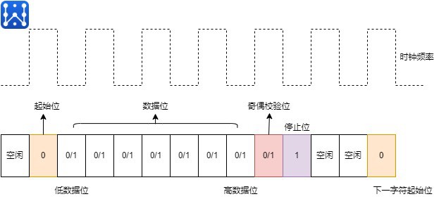
The data of serial communication contains start bit, stop bit, parity bit and data bit. Serial communication is a character by character transmission, each character one by one transmission, and the transmission of a character, always with the "start bit" to start, with the "stop bit" to end, there is no fixed time interval between the characters required.
Each character is preceded by a start bit (low level), the character itself consists of 7 data bits, then the character is followed by a check bit (check bit can be odd, even or no check bit), and finally a one- or one-and-a-half or two stop bits, the stop bit is followed by an indefinite length of the idle bit, the stop bit and the idle bit are specified as high. The actual transmission of each bit of the signal width and the baud rate, the higher the baud rate, the smaller the width, before transmission, both sides must use the same baud rate settings.
baud
Baud (Baud) that is, the modulation rate, refers to the effective data signal modulation carrier rate, that is, the number of carrier modulation state changes per unit time. Baud rate indicates the number of code symbols transmitted per unit of time, it is a measure of the symbol transmission rate, which is expressed in terms of the number of carrier modulation state changes per unit of time, the baud rate refers to the number of symbols transmitted per unit of time. Baud rate can be interpreted as the number of code elements of data a device sends (or receives) per unit of time, which is a measure of the symbol transmission rate, indicating the number of symbols transmitted per unit of time (symbol transmission rate). Typical serial port baud rates are 600bps, 1200bps, 2400bps, 4800bps, 9600bps, 19200bps, 38400bps.
data bit
This is a parameter that measures the actual data bits in the communication. When a computer sends a packet of information, the actual data will often not be 8 bits; the standard values are 6, 7 and 8 bits. How you set this depends on the information you want to send. For example, the standardASCII codeis 0 to 127 (7 bits). The extended ASCII code is 0 to 255 (8 bits)
stop bit
Used to indicate the last bit of a single packet. Commonly used values are 1 bit, 1.5 bits and 2 bits. Why is this stop bit used? Because the data is timed on the transmission line, and each device has its own clock, it is likely that the two devices are slightly out of sync during communication. Therefore, the stop bit not only indicates the end of the transmission, but also provides the computer with the opportunity to correct the clock synchronization, so that the data transmission is more accurate.
check digit
Of course no parity bit is also possible, but the parity bit in the serial communication plays a simple error checking way. There are four types of error checking: even parity, odd parity, high parity and low parity. In the case of even and odd parity, the serial port sets the parity bit (the bit after the data bit) with a value that ensures that the transmitted data has an even or odd logical high bit. For example, if the data is 011, then for even parity, the parity bit is 0, ensuring an even number of logical high bits. For an odd parity, the parity bit is 1, so that there are 3 logic high bits. The high level bit and low level bit checksum will not check the accuracy of the data, but simply through the logic high or logic low checksum, which allows the receiving device to know the status of a bit, there is an opportunity to determine whether there is noise interfering with the communication or whether the transmission and reception of data is not synchronized.
serial port interfacecommunication protocols
Serial communication protocols contain inter-system protocols and internal system protocols; where inter-system protocols are used to communicate between two different devices, just like the communication between a computer and a microcontroller suite, through an internal bus system. The common ones are UART protocol, USART protocol, and USB protocol. Internal system protocols are used to communicate two devices on a circuit board. With the use of in-system protocols, circuit complexity and power consumption are reduced, costs are reduced, and access to data is very secure. The common ones are I2C protocol, SPI protocol, CAN protocol.
Seiden Technology Related Serial Products


Content review.