


summarize
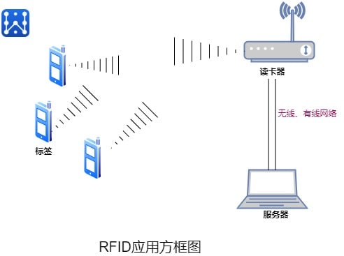
RFID (Radio Frequency IDentification) technology is widely used for electronic identification and tracking. In manyIndoor positioning technologyThe cost advantages and the relative simplicity of installing the equipment have led to a wide range of applications. Especially inWarehousing and logisticsindustry, RFID enables automated inventory and tracking in the supply chain provides substantial advantages. Data can be stored and retrieved remotely on RFID tags, thus realizing real-time identification of equipment and users, identification information associated with the location, the use of RFID will be greatly optimized. Its working principle is relatively simple, the tag into the magnetic field, receive decoder issued by the radio frequency signals, by virtue of the energy gained by the inductive current to send out the product information stored in the chip (PassiveTag, passive tags or passive tags), or take the initiative to send a certain frequency of signals (Active Tag, active tags or active tags); the decoder reads the information and decodes it, and then sends it to the central information system for data processing. Centralized information system for data processing.
History of RFID
1945.Leon Tremont(Leon Theremin invented the "Thing", a Soviet listening device that retransmitted radio waves by adding audio information. The sound waves vibrated a diaphragm, which slightly changed the shape of the resonator, thereby modulating the reflected radio frequency. Although the device was a covert listening device rather than an identification tag, it is considered a precursor to RFID, which is passive and activated by electromagnetic waves from an external source. Similar technologies, such as transponders for identifying friend or foe, were frequently used by the Allies and Germany in World War II to identify whether an aircraft was friendly or hostile, and this is the transponder still used by most powered aircraft.
Early efforts to explore RFID wereHarry Stockman's landmark 1948 paperHe predicted that "a great deal of research and development will have to be done before the remaining fundamental problems in reflected power communications can be solved.
Mario W. Cardullo's device, patented on January 23, 1973, was the first true ancestor of modern RFID, as it was a passive radio transponder with a memory. The original device was passive, powered by an interrogation signal, and was demonstrated to the Port Authority of New York and other potential users in 1971. It consisted of a transponder with a 16-bit memory used as a toll collection device.Cardullo's basic patent covered the use of RF, sound, and light as transmission carriers.The original business plan submitted to investors in 1969 demonstrated the use of the transponder in transportation (automotive vehicle identification, automated toll collection systems, electronic license plates, electronic manifests, vehicle routing, vehicle performance monitoring), banking (electronic checkbook, electronic credit card), security (personnel identification, electronic credit card), and other applications. electronic credit cards), security (personnel identification, automatic doors, surveillance) and medical (identification, patient history).
Early demonstrations of reflected power (modulated backscatter) RFID tags, both passive and semi-passive, were conducted by Steven Depp, Alfred Koelle, and Robert Frayman at Los Alamos National Laboratory in 1973. The portable system operates at 915 MHz and uses 12-bit tags. This technology is used by most UHF UHFID and microwave RFID tags today.
The first patent related to the abbreviation RFID was granted in 1983Charles Walton
Seco et al. 2010 achieved a median positioning accuracy of 1.5 meters based on 71 active RFID tags covering 55 1600 m2 rooms. Describing the spatial correlation with a Gaussian process, they improved the accuracy by 30% compared to least square minimization in RSSI signals propagated indoors.
Kimaldi offered a solution for hospital applications in 2011 based on microwave band static active readers. These tags can be worn as wristbands or attached to key rings for access control and personal monitoring
Operating frequency of RFID systems
RFID signals cannot interfere with the normal operation of other systems, so it uses a frequency band that isISM (Industrial Scientific and Medical) band. It operates at 125kHz, 133kHz, 13.56MHz, 27.12MHz, 433MHz, 2.45GHz, and 5.8GHz, among others.
Low frequency (LF: 125-134.2 kHz and 140-148.5 kHz) (LowFID) tags and high frequency (HF: 13.56 MHz) (HighFID) tags do not require a license to be used worldwide. The identification distance of LowFID and HighFID tags is generally less than 1 meter.
UHF (UHF: 865-928 MHz) (Ultra High FID or UHFID) tags cannot be used globally because there is no single global standard and regulations vary from country to country, and identification distances can be up to 10 meters.
Microwave electronic tag's working frequency is 2.45GHz and 5.8GHz, common recognition distance is 4~6m, recognition distance can be up to more than 10 meters
RFID technology standards
To avoid harm to humans and animals, RF transmissions need to be controlled. Many organizations have set standards for RFID, includingInternational Organization for Standardization (ISO)(math.) genusInternational Electrotechnical Commission (IEC)(math.) genusASTM InternationalThe DASH7 Coalition andEPCglobal. Guidelines have also been developed for a number of specific industries, includingFinancial Services Technology Consortium (FSTC)for tracking IT assets using RFID, CompTIA, the Computer Technology Industry Association, for certifying RFID engineers, and IATA, the International Airline Transportation Association, for airport luggage.
Each country/region can set its own rules for frequency allocation for RFID tags and not all radio frequency bands are available in all countries/regions. These frequencies are called ISM bands (Industrial Scientific and Medical bands). The return signal from the tag may still cause interference to other radio users.
- ISO 11784/11785 :Animal identification. Uses 134.2 kHz.
- ISO 14223 . RFID for Animals . Advanced Transponder
- ISO/IEC 14443: This standard is a popular HF (13.56 MHz) standard for high international densities and is used as the basis for RFID-enabled passports according to ICAO 9303. The Near Field Communication standard that allows mobile devices to act as RFID readers/transponders is also based on ISO/IEC 14443.
- ISO/IEC 15693: This is also a popular high-frequency (13.56 MHz) standard for high FIDs widely used in contactless smart payments and credit cards.
- ISO/IEC 18000: Information technology - Radio frequency identification for project management:
- ISO/IEC 18092 Information technology - Telecommunications and information exchange between systems - Near field communication - Interfaces and protocols (NFCIP-1)
- ISO 18185: This is the industry standard for tracking electronic seals or "e-seals" on cargo containers using 433 MHz and 2.4 GHz frequencies.
- ISO/IEC 21481:Information technology - Telecommunications and information exchange between systems - Near field communication interfaces and protocols - 2 (NFCIP-2)
- ASTMD7434: Standard Test Method for Determining the Performance of Passive Radio Frequency Identification (RFID) Transponders on Palletized or Unitized Loads
- ASTMD7435: Standard Test Method for Determining the Performance of Passive Radio Frequency Identification (RFID) Transponders on Loading Containers
- ASTMD7580: Standard Test Method for Rotary Stretch Packaging Methods for Determining the Readability of Passive RFID Transponders on Homogeneous Pallets or Unitized Loads
- ISO 28560-2 :Specifies the encoding standard and data model to be used in the library.
- To ensure global interoperability of products, several organizations have established additional standards for RFID testing. These standards include conformance, performance and interoperability testing
Wireless Network Positioning Principle
Radio propagation in indoor environments encounters many problems such as severe multipath, line-of-sight (LOS) paths, absorption, diffraction and reflection. Since signals cannot be measured very accurately, several articles have proposed severalinterior positioningAlgorithms. They can be divided into three categories:distance judgment, scene analysis and proximity methods.
Distance estimation
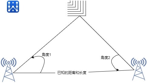
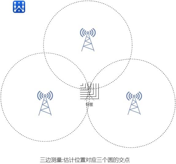
This family of algorithms uses the properties of triangulation to estimate the location of a target. The triangulation method shown in Figure 1 consists of measuring the angle of incidence (or angle of arrival- AOA) at least two reference points. The estimated position corresponds to the intersection of the lines defined by the angles. In contrast, the lateral method shown in FIG. 2 estimates the position of a target by estimating the distance of the target from at least three reference points. The distance measurement technique uses received signal strength (RSS), time of arrival (TOA), time difference of arrival (TDOA), or received signal phase (RSP).
RSS.RSS (Received Signal Strength) The attenuation of the transmitted signal strength is a function of the distance between the transmitter and receiver. Therefore, a target can be localized using at least three reference points and the corresponding signal path loss due to propagation. Several empirical and theoretical models have been proposed to translate the difference between the transmitted and received signal strengths into distance estimates. RSS-based systems usually require field adaptation to minimize the severe effects of multipath fading and shadowing in indoor environments.
TOA.TOA (Time Of Arrival) The distance between the reference point and the target is also proportional to the propagation time of the signal. TOA-based systems require at least three different measurement units to perform lateral measurements for 2D localization. However, they also require that all transmitters and receivers are precisely synchronized and that the transmitted signals include time stamps in order to accurately assess the distance traveled. If more than three reference points are available, the least squares algorithm or one of its variants can be used to minimize the positioning error
TDOA.The principle of TDOA (Time Difference of Arrival) lies in determining the relative position of a target transmitter by using the difference in the time it takes for the signal emitted by the target to arrive at multiple measurement units. Three fixed receivers give two TDOAs, thus providing an intersection point which is the estimated position of the target. This method requires an accurate time reference between measurement units. Like TOA, TDOA has other disadvantages. In indoor environments, LOS channels are rarely available. In addition, radio propagation often suffers from multipath effects, which affect the time of flight of the signal.
RSP:The RSP (Received Signal Phase) method, also known as POA (Phase Of Arrival), uses delay, expressed as a fraction of the signal wavelength, to estimate distance. It requires transmitters to be placed at specific locations and assumes that they emit purely sinusoidal signals. Localization can be performed using phase measurements and the same algorithms as TOA or phase difference measurements and the same algorithms as TDOA. When applied to indoor environments, the disadvantage of the RSP method is that it very much requires LOS signal paths to limit the localization error.
AOA:: AOA (Angle Of Arrival) consists of calculating the intersection of several directional lines, each from a beacon station or target. At least two angles of the directional lines need to be measured and converted into directional lines using a directional antenna or antenna array to find the 2D position of the target. However, this technique requires complex and expensive equipment and is significantly affected by shadowing and multipath reflections.
Scenario Analysis
The scenario analysis method consists of two distinct steps. First, information about the environment (fingerprints) is collected. Then, the location of the target is estimated by matching online measurements with an appropriate set of fingerprints. Usually, RSS-based fingerprinting is used. The two main fingerprint-based techniques are:KNN (k-nearest neighbor nearest neighbor) also known as radio maps and probabilistic methods
kNN methodlies in the first measurement of RSS at a known location in order to build the RSS database known as the radio map. Then, in the on-line phase, RSS measurements linked to the target are performed in order to search for the k closest matches in the previously established signal space. Finally the root mean square error principle is applied to the selected neighbors to find the estimated position of the target.
probabilistic approachThe problem described in is to find the location of the target based on a posteriori probability and Bayesian formulae, assuming n possible locations and a vector of observed signal strengths in the online phase. Therefore, the location with the highest probability is selected. In general, the probabilistic approach consists of different phases such as calibration, active learning, error estimation and history tracking
Approach
The last localization technique in indoor environments is based on proximity. This method relies on a dense deployment of antennas. When a target enters the radio range of a single antenna, its position is assumed to be the same as that receiver. When more than one antenna detects a target, that target is assumed to be at the same location as the antenna receiving the strongest signal. This method is very basic and easy to implement. However, the accuracy is very dependent on the order of magnitude of the antennas.
Indoor positioning using RFID
together withWi-Fi positioning(math.) genusBluetooth Low Energy (BLE) localizationmaybeUltra Wide Band (UWB)In contrast to positioning technologies such as RFID tracking, RFID tracking only supports point positioning due to its restricted height range of less than one meter. This means that objects equipped with RFID tagsCan only be located at specific checkpoints - Regardless of where the RFID hardware readers have been installed. Possible applications therefore include systems for access control, time recording or inventory control in logistics, but not continuous route tracking or seamless tracking over larger areas.
Passive RFID systems rely solely on inductive coupling and therefore do not require batteries. The principle of inductive coupling allows tags to receive enough energy in the form of RF waves from a nearby RFID scanner to send their code back to the scanner. Passive tags can be applied to waypoint navigation based on an id-tagged reference grid, where the ID-tagged location can be accessed from a database. The advantages of using passive RFID tags for positioning are their small size, high strength, relatively inexpensive installation, and low maintenance requirements because they have no batteries. Passive tags are therefore suitable for underground embedding in building materials. The main disadvantage is that the detection range is usually limited to 2 meters, which requires dense deployment of tags. The attenuation of embedded tags increases with frequency, e.g., for frequencies above 2.4 GHz, the application of concrete embedded tags is prohibited. Below 100 MHz, the attenuation of embedded tags is low and comparable to that of free space, but frequencies below 300 MHz are unsuitable for read ranges above 1 meter because inductive coupling is a phenomenon of near-field operation. Penetration of electromagnetic waves in concrete depends on the use of integrated metal fibers, the water content of the walls, floors and ceilings, and the angle of incidence of the radio waves.
The positional accuracy of an RFID system (i.e. its ability to locate an object in space) will depend on the type of RFID system you are referring to. In general, most passive HF and UHF RFID systems do not provide positional accuracy - they tell you that a tag has been read by a specific reader. Since you know the location of a reader by its unique ID (e.g., Docking Gate A), you will know that the tag is in the read zone of that reader (i.e., the tagged item is from Docking Gate A).
There are a number of passive UHF Real Time Location Systems (RTLS) that can tell you where a tag is in 3D space. These are usually accurate to within a meter cube. These passive systems may each cover 10 square meters, so you need multiple readers to cover 50 square meters.
RFID-based active RTLS have tags that use a battery broadcast signal. Readers around a defined area triangulate that signal and pinpoint its location. Because the tag sends out a signal like a cell phone, the tag can be read from much greater distances (1,000 meters or more). You can cover large areas with fewer readers than with passive RTLS, but the tags cost more. Positioning accuracy of active RTLS is typically within 3 meters
Future Directions for RFID Positioning Technology
Universal networks are potentially rich as far as information is concerned. The number and diversity of its components can be used to increase the accuracy of RFID localization. Therefore, future localization approaches should consider several aspects.
- RF modelMost current methods perform RSS measurements. However, they usually use models developed for wireless networks. there are some peculiarities of RFID propagation that should be taken into account in a proper RF model.
- Card reader redundancyIn response to the dense deployment of card readers, card reader redundancy should be utilized more often to obtain more data
- Card reader diversityThe localization in RFID networks with readers of different read ranges, antennas and capacities may be an interesting and more realistic approach.
- Intelligent Restrictionsthat can be deduced from meta-information. For example, two labels fixed to the same package define the physical distance boundaries between them.
- mobility, a hybrid system with static and mobile readers should be considered to increase the amount and diversity of data collected.
scalabilityThe scalability of RFID positioning technology should be scrutinized in order to define the number of tags that can be read in a given cycle; the rate of successful reads, their impact on accuracy, and how long it takes for positioning calculations to be performed.
standard measureFinally, RFID positioning solutions cannot be directly compared because they are based on different assumptions. The criteria needed to accurately measure a positioning solution are accuracy and the cost of the overall system.
RFID Basics-A Prim er on RFI D
Content review.