Active RFID 485 to Ethernet Network Reader Base Station WE-RN01

 Product Features

  • It can detect 500 electronic tags at the same time, and the antenna detection distance can reach 100 meters in the open.
  • The wireless signal field strength of the electronic tag can be measured and the actual distance of the tag can be calculated.
  • Tags can be called for audible and visual alerts (audible and visual tags only)
  • The readout antenna can be extended up to 50 meters (9600bps) for easy installation and deployment.
  • Through the RS485 interface can be accessed 32 485 card reader, good expansion performance.
  • Provides open protocols so that third-party systems can easily communicate with the reader over the network.
  • Provide SDK development kit, convenient for users to develop their own label positioning management system.
  • Wide voltage supply from 10 to 26V, each card reader consumes no more than 500mA (12V)

¥585

Product Overview

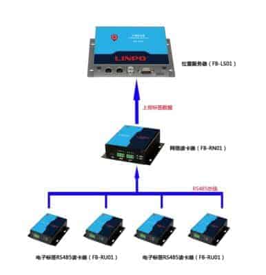
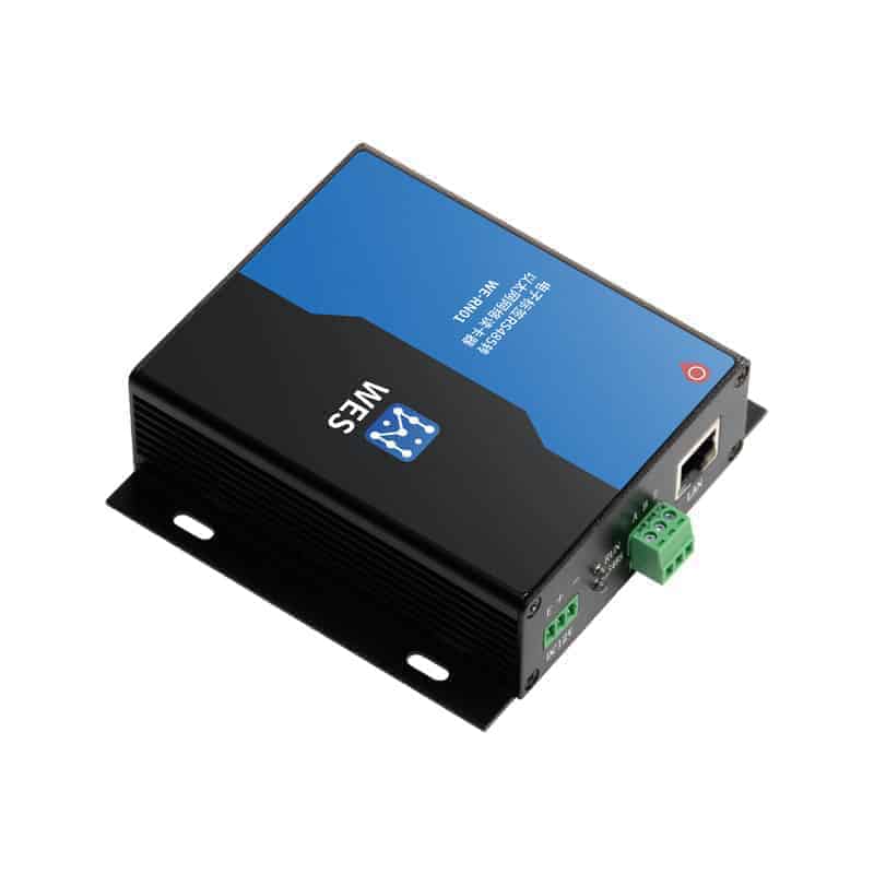
WE-RN01 network reader can be installed with two reading antennas, and the distance of detecting tags can be up to 100 meters in the open. The reader not only can read the ID value of the electronic label, but also can calculate the actual distance of the label by measuring the wireless signal field strength of the electronic label. A number of readers work together, you can determine the effective range of the specific location of the electronic tags, to achieve real-time monitoring of the location of personnel, goods, convenient personnel, goods tracking and finding.

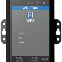
The RS485 interface of WE-RN01 network reader can access 32 RS485 readers, together with the 2 reading antennas of the device itself, a total of 34 positioning base stations can be deployed in one network reader, which can cover an area or a floor, and easily realize the monitoring and positioning of the tags in the whole area.

Application Areas

Tag positioning is widely used in many applications such as intelligent warehouse management, logistics tracking, indoor navigation, and people management.

Distance measurement formula

This product calculates the distance between the electronic tag and the antenna by measuring the wireless signal field strength of the tag, and the distance and the wireless signal strength are in an exponential curve relationship as follows:

Due to chart size limitations, only correspondences within a distance of 7 meters are shown

In the above graph, there are 3 values that we need to measure repeatedly to calibrate.
1. L0: The signal strength when the distance between the tag and the reader is 0 cm, the measured value is -8dBm.
2.L1: Signal strength when the distance between the tag and the reader is 40cm, measured value is -20dBm.
3.L2: Signal strength when the distance between the tag and the reader is 100cm, measured value is -30dBm.
Based on these three values, the derived formula is as follows:

Positioning Properties

specification

sports event norm
indicator light Running light, normally on (occasional flash) is on-line normal, normally off (occasional flash) is on-line abnormal.
RS485 interface working indicator, the light is on then the 485 interface is working normally.
Read antenna operating indicator, blinks every time a tag signal is read.
Ethernet interface 10M/100M Adaptive
Supports DHCP, UDP, TCP, IP, HTTP protocols.
Provide SDK development kit, support access to third-party systems
RS485 interface Baud rate can be set to 9600, 19200, 38400, 57600, 115200bps
Communication distance over 800 meters
Supports handheld access to multiple RS485 readers (up to 32)
Reader Antenna Interface Communication interface RS232 serial port
Communication baud rate 115200, 57600, 38400, 19200, 9600bps
Interface specification 4P terminal header (5V, ground, serial transmit, serial receive)
Operating temperature and humidity -40℃~85℃, humidity less than 95% (no condensation)
Installation Ceiling Mount/ Wall Mount
power supply (of an appliance etc) 12V (0.5A), supports DC10V-DC26V wide voltage supply
sizes 82mm x 103mm x 33mm (excluding both sides fixing lugs)
weights 250g

blueprint

Installation dimensions

hardware interface


connector name (of a thing) norm clarification
Configure the interface SET miniUSB port Connect to the computer with USB and run the configuration software on the computer to modify the device parameters.
Read Antenna Interface ANT0/1 G Power Ground (Output) 3.5mm terminal block to connect the FB-TX20 card reader antenna.
R RS232 data reception
T RS232 data transmission
V Power supply 5V (output)
Power connector DC12V E Earth (generally not connected) 3.5mm terminal block, voltage range 10V~26V (12V recommended)
+ Power Supply Positive (12V)
POWER GROUND
Ethernet interface LAN 10/100M Adaptive Reporting of label data through the web interface
RS485 bus interface A A signal for RS485 interface 3.5mm terminal block, connects to RS485 bus, can access 32 FB-RU01 readers.
B B signal for RS485 interface
E Earth (generally not connected)
indicator light RUN Equipment operation indicator Normal light (even flash) equipment online normal; often off (even flash) equipment online abnormal
RS485 RS485 interface indicator A constant light indicates that the RS485 bus is working normally.
ANT0 No. 0 Read Antenna Indicator Receive a flash of tag data, the more tags the faster it flashes.
ANT1 No. 1 readout antenna indicator

Networking Description

FB-RN01 reader can be extended by 32 RS485 readers FB-RU01 through RS485 interface, including itself (the device itself can be connected to 2 reading antennas), a network reader can have up to 34 location base stations. RS485 reader will read the tag information reported to the network reader, and then the network reader will report all the tag information to the location server, the location server will synthesize the data and come up with the specific location of the tag. The location server will synthesize the data and arrive at the specific location of the tags.

The FB-RN01 wired reader is connected to a network reader via the 485 bus, and whichever network reader it is accessed by becomes a substation under that network reader. An FB-RN01 network reader can have up to 34 substations, each of which is an independent positioning base station.

The network reader itself can be connected to 2 reading antennas, occupying two substations, No. 0 and No. 1. Then expand up to 32 FB-RU01 wired readers through 485 bus, each wired reader occupies 1 substation number.FB-RU01 wired reader has a 5-digit dialer which can dial out the value of 0~31, corresponding to substation No. 2~33 respectively, as detailed below:

substation number dialer substation number dialer substation number dialer substation number dialer
0 Network Card Reader ANT0 1 Network Card Reader ANT1
2 0 0 0 0 0 3 0 0 0 0 1 4 0 0 0 1 0 5 0 0 0 1 1
6 0 0 1 0 0 7 0 0 1 0 1 8 0 0 1 1 0 9 0 0 1 1 1
10 0 1 0 0 0 11 0 1 0 0 1 12 0 1 0 1 0 13 0 1 0 1 1
14 0 1 1 0 0 15 0 1 1 0 1 16 0 1 1 1 0 17 0 1 1 1 1
18 1 0 0 0 0 19 1 0 0 0 1 20 1 0 0 1 0 21 1 0 0 1 1
22 1 0 1 0 0 23 1 0 1 0 1 24 1 0 1 1 0 25 1 0 1 1 1
26 1 1 0 0 0 27 1 1 0 0 1 28 1 1 0 1 0 29 1 1 0 1 1
30 1 1 1 0 0 31 1 1 1 0 1 32 1 1 1 1 0 33 1 1 1 1 1

Application matching

The following products are our various types of labels, this product can not be used alone, you need to cooperate with our various card readers to meet your actual scene requirements

maybeContactsThe sales staff of the company will give you reference advice:

Resource support

Documentation:
Electronic Tag Network Reader WE-RN01 Product Manual

Software:
software package
Software source code (ask customer service for it)
secondary development kit
A new version of the Internet

Case Study

en_USEnglish